APPENDIX A: TECHNICAL SPECIFICATIONS
MODEL 250DP DUAL PULSE
RESISTANCE WELDING POWER SUPPLY
A-16
990-280
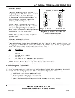
The CONTROL SIGNALS connector ( figure A-5) is
a Viking DMRST15RA05CG (Unitek Peco PN 250-
195). The mating connector, which included in the
shipping kit, is a TRW Cinch Connector comprised of
a DA-15P (Unitek Peco PN 250-199) male connector
and a DE-51210-1 (Unitek Peco PN 250-200) plastic
junction shell. The pin assignments are listed below:
Pin
Function
1
Remote Weld Schedule Selection, Control Line 2
0
2
Remote Weld Schedule Selection, Control Line 2
1
3
Remote Weld Schedule Selection, Control Line 2
2
4
Remote Weld Schedule Selection, Control Line 2
3
5
Remote Weld Schedule Selection, Control Line 2
5
6
Relay 2 Input
7 No
Connection
8
Relay 1 Input
9
Process and Charge Inhibit
10
Emergency
Stop
11
Signal and Chassis Ground
12
Remote Weld Schedule Selection, Control Line 2
4
13
RELAY 2 Return
14
Remote Weld Schedule Selection, Control Line 2
6
15
RELAY 1 Return
Emergency Stop
Emergency stop, or any other external function that should abort the welding sequence, can be
implemented by continuously shorting Pin 10 to Pin 11 of the CONTROL SIGNALS connector. If
either Pulse 1 or Pulse 2 has been initiated before the emergency stop signal occurs, that pulse will not
be interrupted. After that, no further operation can be initiated until the short has been removed.
8
1
9
15
Figure A-5. CONTROL SIGNALS
Connector


