APPENDIX A: TECHNICAL SPECIFICATIONS
MODEL 250DP DUAL PULSE
RESISTANCE WELDING POWER SUPPLY
990-280
A-3
Over-Voltage Lockout
Protects the capacitor bank from damage due to circuit malfunction or improper calibration. The circuit
breaker opens, removing primary power, and the line failure turndown circuit automatically discharges
the capacitor bank. The circuit is adjusted to operate when 440 ± 1 volts is placed across the capacitor
bank.
Charge Lockout Circuit
Nominal 60 millisecond commutation pulse, generated in the microprocessor, inhibits the charging
circuit until the output SCR has been switched off.
Polarity Selection
Positive (+) and negative (-) polarity can be specified for each weld schedule. Polarity sets the initial
direction of the weld current flow through the workpiece. This feature is useful for welding applications
which are sensitive to the direction of weld current flow because of dissimilar materials and/or materials
with thickness ratios greater than 4 to 1.
Welding Speed
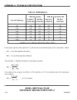
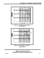
Repetition rate is the average number of welds allowable in 1 minute based upon the thermal rating of the
system components. The averaging period used to determine the repetition rate can be as long as 20
minutes. Hit rate, or maximum intermittent welding speed, defines how fast the power supply can make
consecutive welds on a non-continuous basis. See table A-2 and figures A-1 and A-2.

