CHAPTER 2: INSTALLATION
MODEL 250DP DUAL PULSE
RESISTANCE WELDING POWER SUPPLY
990-280
2-3
Rear Panel Components
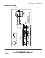
The input and output connections located on the rear panel of the 250DP (figure 2-3) are listed below.
A CONTROL SIGNALS: 15-pin, subminiature D-type connector used for remote schedule selection,
output relays, process inhibit and emergency stop (refer to Appendix A under
Control Signals
).
B ACCESSORY PORT: 25-pin, subminiature D-type connector used to interface with other Unitek
Peco devices.
C OPTICAL FIRING SWITCH: 5-pin receptacle is used to connect the 250DP to weld heads with
either a 3-wire firing switch or an optical switch.
D AIR VALVE DRIVER 2: Provides 24 VAC to control a second Unitek Peco air actuated weld head.
E AIR VALVE DRIVER 1: Provides either 24 or 115 volts (AC) to control a Unitek Peco air actuated
weld head.
PO W ER
CB 1
CB 2
CO NT RO L SIG NA L ;S
ACC ESSO R Y PO R T O P TIC AL FI RING SW IT CH
AIR VA LV E D RIVER
1
2
F OO T SW IT CH
ME CH ANICAL
F IRING S W ITC H
A
B
C
D
E
J
F
G
I
H
Figure 2-3. Rear Panel Components

