background image

INSTRUCTION MANUAL

MODEL  PS1550

FAULT TOLERANT POWER SUPPLY

For Mission Critical Applications

Instruction Manual 114/GB - PN. 991204        

DOC. TEC.

IItta

ally

y  H

He

ea

ad

dq

qu

ua

arrtte

errss

Fuchs Elcon 
Via delle Industrie, 4 • 20050 Mezzago (MI) - Italy
Tel. +39 039 6292 1  • Fax +39 039 6292 240
e-mail: [email protected]

W

Wo

orrlld

dw

wiid

de

e  H

He

ea

ad

dq

qu

ua

arrtte

errss

Fuchs GmbH • Königsberger Allee 87
68307 Mannheim - Germany
Tel. +49 621 776-0 • Fax +49 621 776-10 00

http://www.pepperl-fuchs.com
e-mail: [email protected]

U

US

SA

A  H

He

ea

ad

dq

qu

ua

arrtte

errss

Fuchs Inc. • 1600 Enterprise Parkway
Twinsburg, Ohio 44087 • Cleveland - USA
Tel. +330 425 35 55 • Fax +330 425 46 07

A

Assiia

a  P

Pa

acciiffiicc  H

He

ea

ad

dq

qu

ua

arrtte

errss

Fuchs Pte Ltd • P+F Building
18 Ayer Rajah Crescent • Singapore 139942
Tel. +65 779 90 91  • Fax +65 873 16 37

Subject to reasonable modifications due to technical advances • Copyright FUCHS ELCON • Printed in Italy • IM-ENG-114/GB-AO-PN991204

www.elconinstruments.com

Содержание PS1550

Страница 1: ...87 68307 Mannheim Germany Tel 49 621 776 0 Fax 49 621 776 10 00 http www pepperl fuchs com e mail info de pepperl fuchs com U US SA A H He ea ad dq qu ua ar rt te er rs s Pepperl Fuchs Inc 1600 Enterprise Parkway Twinsburg Ohio 44087 Cleveland USA Tel 330 425 35 55 Fax 330 425 46 07 A As si ia a P Pa ac ci if fi ic c H He ea ad dq qu ua ar rt te er rs s Pepperl Fuchs Pte Ltd P F Building 18 Ayer R...

Страница 2: ... 15 5 10 1550 RFD CHASSIS 15 ELECTRICAL CONNECTIONS 17 6 1 POWER CONNECTIONS 17 6 2 INDICATION OF POWER FAILURE 18 6 3 ALARM CONNECTION 18 6 4 OUTPUT CONNECTIONS 18 OPERATING INSTRUCTIONS 19 7 1 PRELIMINARY CONTROLS AND CONNECTIONS 19 7 2 ISOLATION TESTING 19 7 3 STARTING UP 20 MAINTENANCE 20 8 1 SPARE PARTS 21 8 2 REPAIRS 21 8 3 TROUBLESHOOTING 22 WARRANTY 24 REV A0 20 OCTOBER 99 I N D E X 1 2 3 ...

Страница 3: ... If not installed the equipment should be stored according to the indications reported in the following paragraph storage IM ENG 114 GB 1 INTRODUCTION 2 UNPACKING If storaging instrumentation or accessories adequate precautions must be taken to protect them from damage Keep instrumentation in sealed original package until installed See that adequate protection is taken to prevent da mage from expo...

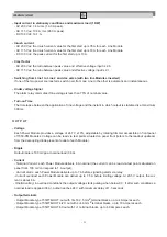
Страница 4: ...fficient system typical yield 80 with minimum heat dissipation Moreover the system Limits the inrush current value during the first start up by NTC at 15Ω 2W Is protected against power surges by a varistor with energy absorption of 71 Joules in 2 ms Is protected against shortcircuiting at output pushbutton function Is thermically protected each Power Module has its own thermal protection of 85 C T...

Страница 5: ...ower front side When the panel is opened a mi croswitch interrupts power supply to fans permitting easy access without risk If one of the fans breaks down the corresponding green LED function indicator is set OFF and the alarm relay is activated 4 3 SPECIFICATIONS I N P U T Input voltage Line 1 and or Line 2 AC 230 Vac nominal 15 195 264 Vac at 47 63 Hz AC 115 Vac nominal 15 97 5 132 Vac at 47 63 ...

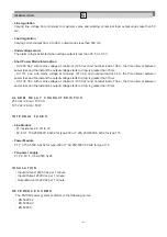
Страница 6: ... P U T Voltage Each Power Module provides a voltage of 24 7 V 10 adjustable by rotating trimmer accessible on front panel of 1550 PM Modules Voltage can be read via test points situated on panel front refers to the readout upstream from the decoupling diode present at outlet of each Module Ripple Output ripple is 100 mVpp at nominal load 36 A Current Nominal Current each Power Module delivers 6 A ...

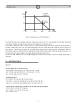
Страница 7: ...e instant the output voltage starts to drop is greater than 15 ms AC 130 Vdc with mains voltage at minimum 100 Vdc and nominal load of 36 A the time interval between power loss and the instant the output voltage starts to drop is greater than 10 ms A L A R M R E L A Y C H A R A C T E R I S T I C S 250 Vac 2 Amp 100 VA 125 Vdc 2 Amp 50 W I N T E R N A L F U S E S Line Module F1 resistance 2 2 Ω 1 2...

Страница 8: ...liability is at any rate guaran teed C STANDARD ALTERNATING CURRENT AND EMERGENCY ALTERNATING CURRENT OR UPS INPUT This solution utilizes standard alternating current as well as an emergency power source it must be activated within 10ms from the loss of the power line or must be an uninterruptible type UPS In order to avoid having the UPS line under permanent charge its voltage output must always ...

Страница 9: ...lue of 20 A during first start up AC 130 Vdc to be able to guarantee each line Module a 16 A voltage peak during first start up CREST FACTOR AC 230 Vac the ratio between peak value and effective value of voltage must be 3 AC 115 Vac the ratio between peak value and effective value of voltage must be 2 5 VOLTAGE IN STATIONARY CONDITIONS AND MAXIMUM LOAD 1 KW AC 230 Vac 8 A rms 21 A peak AC 115 Vac ...

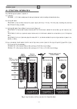
Страница 10: ...ich must of the same version based on the type of system type 230 or type 115 there are two possibilities 1550 LM 230 is the module that permits working with 230 Vac input voltage 1550 LM 115 is the module that permits working with 115 Vac or 130 Vdc input voltage Fig 2 Input module and three versions for Output Modules Circuit board 1550 TB OUT 4 20 is equipped with 4 4 terminals 24Vcc up to 16A ...

Страница 11: ...put TERMINATION OUTPUT MODULE 1 16 1 16 3 4 24 V 0 V Fan failure detector Fan 1 OK Fan 2 OK Fan 3 OK OUT ON OVERLOAD VOLTAGE CURRENT Safety Block Switch Power Line 2 AC DC Power Module 2 Power Module 5 Power Module 6 OUT ON OVERLOAD VOLTAGE CURRENT OUT ON OVERLOAD VOLTAGE CURRENT I M P O R T A N T WHEN TWO POWER LINES ARE UTILIZED LINE 1 MUST BE ISOLATED FROM LINE 2 NO COMMON POINTS OTHERWISE A PO...

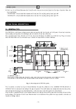
Страница 12: ...The inputs are protected by two time lag fuses 10 A or 20 A respectively based on type of system The voltage once rectified is made available to Power Modules via Mother Board bus IN IN The overall value of the bank of capacitors is enough to guarantee in case of mains failure an interim 15ms output time both for type 230 and type 115 with nominal voltage load 36A The line Modules present a green ...

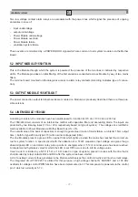
Страница 13: ...concerning one of the two power lines or modules output is at any rate guaranteed by the presence of the second line This result is possible thanks to the block diode on 1550 LM output 5 5 ALARMS Alarm relays and relative command circuit are mounted in line Modules They are 24V relays with output contacts suitable for low voltage connections They are commuted according to POWER GOOD signal level n...

Страница 14: ... Module consists of an insulated DC DC converter which functions in switching mode at a frequency of 330 KHz LAMBDA PH150S 280 24 for type 230 and LAMBDA PH150S 110 24 for type 115 components are utili zed they convert the rectified power supply current present in bus IN IN into 24 V voltage output A filtering stage is present at input of all Power Modules which permits the reduction of conducted ...

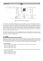
Страница 15: ...e way In reference to figure 5 amplifier A amplifies signal detected in shunt to within 3 and its output pin reaches 5 V when current from Module is equal to 6 A The signal obtained in this manner is then sent to common SHARING bus via unidirectional buffer labeled B The highest SHARING current is thus presented at B for which if the Mo dule in question furnishes low current to others a difference...

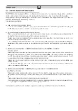
Страница 16: ...r overload the respective LED is set OFF and the POWER GOOD signal lowered stepped down so that alarm relays de energize Failure or mal function is signalled by a 3 second delay A power cut off switch is mounted on the circuit board which interrupts power delivery to fans when panel is ope ned even when panel is open and therefore fans inoperative the signal is relayed to alarm relay 5 9 MOTHER BO...

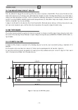
Страница 17: ...UT for mounting panel 285 11 22 The fans and fault detection circuits are mounted under the support panel Detection circuit power connection terminal Fan fault detection circuit Fuse 3 Fuse 2 Fuse 1 Fan 3 Fan 2 Fan 1 LD1 LD3 LD2 Detection circuit power cable 5x20 glass fuses 500 mA Power connection terminals ...

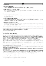
Страница 18: ...nnections or hazardous electrical arcs Verify that no part s of wiring is expo sed or can cause shortcircuiting with ground or other wires Install adequately sized switches 8 Amp for function at 230V 16 Amp for function at 115V on each power line in readily identifiable positions and which can be easily accessed in case of emergency i e repairs If two power lines are connected make sure that two l...

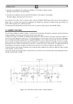
Страница 19: ...on and the restabili zation of normal operative conditions 6 3 ALARM CONNECTIONS For installation where alarms are actuated subsequent to opening of contacts connect the two normally closed contacts in series on input module 1550 TB IN see Fig 10b In this manner without alarm situation the contact remains closed and any alarm will open the series Otherwise if alarm utilizes for activation contact ...

Страница 20: ...lized for output connections must be adequately sized in accordance with maximum voltage reque sted by load and must be firmly connected to terminals without exposed parts which may cause shortcircuiting due to contact with metallic parts C The system must be free of short circuits ALARMS A Alarm circuits must be wired correctly B Wiring for alarm connections must be firmly connected to terminals ...

Страница 21: ...associated equipment Verify that grounding connections are efficient to avoid risk of electrical shock Each line Module contains capacitors with a total capacity of 3300µF for Type 115 1500µF and Type 230 such components loaded at working voltage accumulate lethal energy Before extracting Modules it is therefore neces sary to first disconnect them from Mother Board then pull outward without actual...

Страница 22: ...5 Fuses glass 500 mA PN 501003 5 for fan 5x20 1550 FBD Chassis with 3 fans 24Vcc 5 and fault detection circuit Function Function Spare Parts Description for for 115 V 230 V of installed ELCON PN ELCON PN parts Table 1 8 2 REPAIRS WARNING Repairs not directly carried out by Elcon Instruments are at the sole risk and responsability of the user In addition the terms stipulated in instrument warranty ...

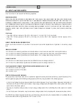
Страница 23: ... from 1 to 6 OK ON Fans OK current absorption within normal limits Fans units 1 2 3 LED green FAN OK OFF Breakdown or overload of respective fan current absorption too high or low LED status and corresponding malfunction diagnosis 8 3 TROUBLESHOOTING The PS1550 power system is fitted with luminous indicators LED and alarm relays which furnish useful indications on system function and help operator...

Страница 24: ...Are other FAN OK indicators OFF Fault in respective Fan or fuse Disconnect load Is 24V output OK Are other OVERLOAD indicators ON Gradual load increase Is load correct Corrective procedure substitute faulty power module LED indicator OUT ON OFF NO YES YES YES NO YES NO Corrective procedure substitute line module Cause overload or shortcircuit on load create excess current NO YES NO YES YES NO YES ...

Страница 25: ...hipping dismnantling and reassembly expenses operations that in any case must be done in accordance with the supplier at the cu stomer s charge In no case will Elcon Instruments be held responsible for expenses for loss of profit and or damage direct or in direct that can be incurred by the customer due to a fault or defect of the material b The warranty is considered invalid for instruments or ma...

Страница 26: ...r equivalent type quality and effi ciency suitable to the same use If the customer refuses such offer without justified motivation he is entitled to reimbursement of the money al ready paid or a refund of real incurred expenses i For items subsupplied by Elcon Instruments the standard warranty terms as given by the original manufacturer are applicable j The warranty must be considered for material...

Отзывы: