- 9 -
IM-ENG-114/GB
4.6 STRUCTURAL INFORMATION
The PS1550 power system consists of:
A) a chassis:
1550/RFD
A 19’’rack predisposed to accept 4 stacked units including extractable fan box.
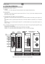
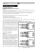
B) an Input Module:
1550/TB-IN is the terminal module for power inputs (230 Vac, 115 Vac, 130 Vdc) also including the terminal
board for alarm relay contacts.
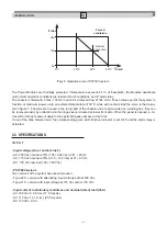
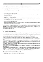
C) an Output Module; three different versions exist (figure 2):
1550/TB-OUT is the standard output module with 16+16 terminals suitable for connections up to 4 Amperes ea-
ch.
1550/TB-OUT 4/20 is an optional output module wih 4+4 terminals suitable for connections up to 16 Amperes
each.
1550/TB-OUT 60 is an optional output module with 1+1 terminals suitable for per a single maximum power con-
nection, (~60 A).
D) two redundancy line Modules which must of the same version; based on the type of system (type-230 or type-
115) there are two possibilities:
1550/LM-230 is the module that permits working with 230 Vac input voltage.
1550/LM-115 is the module that permits working with 115 Vac or 130 Vdc input voltage.
Fig. 2.
Input module and three versions for Output Modules
Circuit board 1550/TB-OUT 4/20
is equipped with 4
÷
4
terminals 24Vcc up to 16A each
OUTPUT
Terminals
24 V
DC
+
+
+
+
c
c
c
c
POSITIVE
COMMON
OUTPUT
24 V
DC
COMMON
+
Alarm
contacts
1
Line
2
Note:
Contacts are indicated
in de-energized state
1 2
~
ON
16
10
11
12
13
14
15
1
2
3
4
5
6
7
8
9
~
~
~
16
10
11
12
13
14
15
1
2
3
4
5
6
7
8
9
0 Volt
+24V
Input
Module
and Alarms
Standard
Output Module
Different output circuit
boards available
Circuit board 1550/TB-OUT 60
is equipped with 2 bolts
24Vcc up to 60A each
Alarm
contacts
2
Line
1
Circuit board 1550/TB-OUT
is equipped with 16
÷
16
terminals 24Vcc up to 4A each
1550/TB-IN
1550/TB-OUT
1550/TB-OUT 4/20
1550/TB-OUT 60


