- 12 -
IM-ENG-114/GB
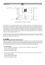
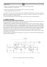
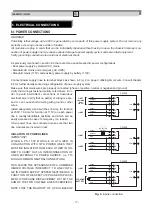
Fig. 4.
Auxiliary power supply in line Modules.
The TOP 223Y is a non isolated simple flyback converter. With reference to figure 4, D4 and DZ4 reduce spikes on
Drain, D3 and C14 rectify and filter voltage output from transformer, while the 24V are controlled by DZ2; D2 pre-
vents loading pin C at start up. C17 carries out more functions: it determines a components starting time, determines
restarting frequency during shortcircuiting, filters the signal to control pin and compensates system. The auxiliary cir-
cuitry including the two transistors Q2 and Q3, avoids any uncertainty during activation and deactivation of
TOP223Y: activating circuit occurs with power supply (voltage at the test capacitors) above 65V ± 10%, while deacti-
vation occurs due to voltage below 55V ± 10%.
The PS1550 is provided with two redundant line Modules so that in case of power failure concerning one of the two
power lines or modules, output is at any rate guaranteed by the presence of the second line. This result is possible
thanks to the block diode on 1550/LM output.
5.5 ALARMS
Alarm relays and relative command circuit are mounted in line Modules. They are 24V relays with output contacts
suitable for low voltage connections. They are commuted according to POWER GOOD signal level: normally they
are activated and only de-energize due to system failure (POWER GOOD passes from high to low state). The varia-
tion of the signal may occur for one or more reasons; various alarm causes are reported in the following.
• Input Undervoltage
The green LED indicator of line Module is on and the alarm relay is activated when values are above:
- 178 Vac ± 3% when mains is 230 Vac
- 93 Vac ± 3% when mains is 115 Vac
- 95 Vdc ± 3% when mains is 130 Vdc
The alarm relay de-energizes and the line Module green LED indicator is set OFF when at nominal load the re-
spective voltage goes below:
- 172 Vac ± 3% when mains is 230 Vac
- 90 Vac ± 3% when mains is 115 Vac
- 92 Vdc ± 3% when mains is 130 Vdc


