- 21 -
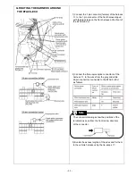
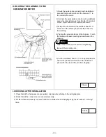
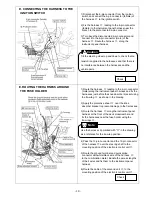
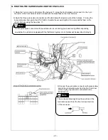
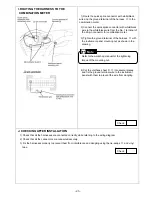
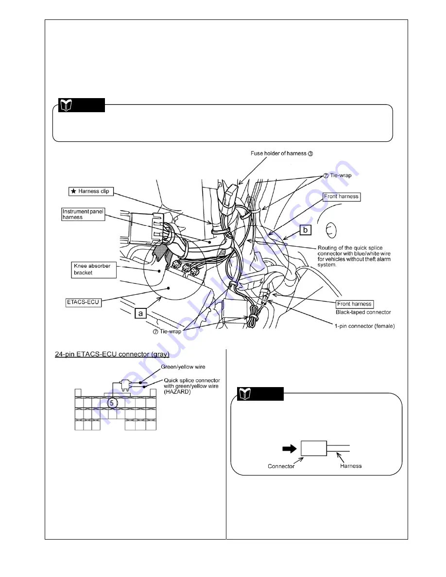
G. ROUTING THE HARNESS AROUND THE ETACS-ECU
1) Route the 1-pin connector (female) of the harness
③
along the front harness and connect it to the 1-pin
connector of the front harness which is taped with the black tape on the front harness.
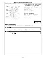
2) Route the three quick splice connectors and the terminal with red/green wire of the harness
③
along the
instrument panel harness to the ETACS-ECU. Bundle the excess lengths of the wires and fix them to the
vehicle harness using the tie-wraps
⑦
.
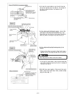
3) Connect the quick splice connector with green/yellow
wire to the green/yellow wire from the No. 5 terminal
of the 24-pin gray connector connected to the
ETACS-ECU.
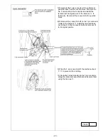
For the quick splice connector with blue/white wire, its connecting point and routing differs depending
on whether the vehicle is equipped with the theft alarm system or not. Details will be described in step 5).
Note
The connector drawings show the positions of the
terminals as seen from the front (arrow direction)
of the connector.
Note
Содержание MZ360360EX
Страница 6: ... 6 ...
Страница 7: ... 7 ...
Страница 16: ... 16 ...
Страница 17: ... 17 ...
Страница 28: ... 28 ...
Страница 29: ... 29 ...
Страница 42: ... 42 Circuit Diagram ...
Страница 43: ... 43 ...
Страница 44: ... 44 Troubleshooting P 38 step 2 ...
Страница 45: ... 45 P 38 step 2 3 ...
Страница 46: ... 46 P 41 step 3 3 ...
Страница 47: ... 47 P 51 terminal No 3 P 51 ...
Страница 48: ... 48 P 51 P 51 terminal No 13 ...
Страница 49: ... 49 P 51 terminal No 24 P 51 terminal No 18 ...
Страница 50: ... 50 ...

