- 34 -
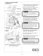
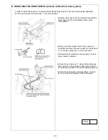
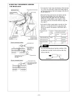
4) Bundle the excess lengths of the wires and fix them
to the instrument panel harness using the tie
-
wraps
⑦
.
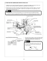
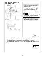
5) Disconnect the 3-pin connector of the instrument
panel harness from the junction block. Draw out the
No. 3 terminal from the connector and install the
terminal with red/green wire of the harness
③
to
that cavity. Reconnect the connector to the junction
block.
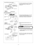
6) Disconnect the connector half on the 1-pin connector
(male) of the harness
③
. Install the terminal drawn
out in step 4) to that connector half and reconnect it
to its original position.
7) Wrap the urethane tape C
④
around the 1-pin
connector to prevent rattling.
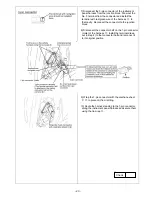
8) Fix the 1-pin connector harness as shown in the
drawing using the tie-wraps
⑦
.
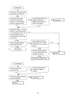
Check
Содержание MZ360360EX
Страница 6: ... 6 ...
Страница 7: ... 7 ...
Страница 16: ... 16 ...
Страница 17: ... 17 ...
Страница 28: ... 28 ...
Страница 29: ... 29 ...
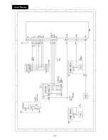
Страница 42: ... 42 Circuit Diagram ...
Страница 43: ... 43 ...
Страница 44: ... 44 Troubleshooting P 38 step 2 ...
Страница 45: ... 45 P 38 step 2 3 ...
Страница 46: ... 46 P 41 step 3 3 ...
Страница 47: ... 47 P 51 terminal No 3 P 51 ...
Страница 48: ... 48 P 51 P 51 terminal No 13 ...
Страница 49: ... 49 P 51 terminal No 24 P 51 terminal No 18 ...
Страница 50: ... 50 ...

