- 2 -
■
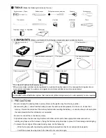
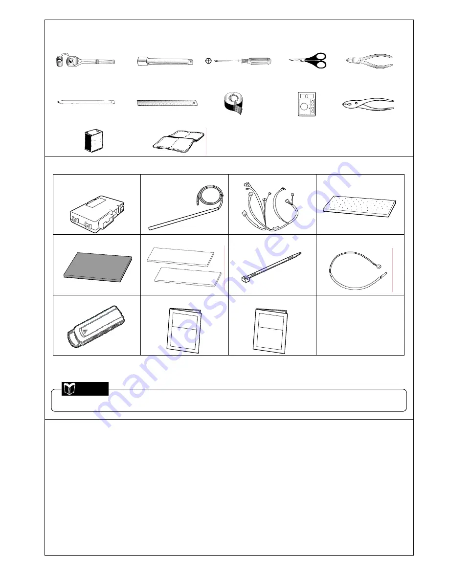
TOOLS
(Make the following tools ready for use.)
Socket wrench (10mm)
Extension bar
Phillips screwdriver (medium)
Scissors
Cutting pliers
Trim remover
Scale
Vinyl tape
Multimeter Pliers
Isopropyl alcohol or degreaser Shop towel
■
COMPONENTS
(Make sure that all of the following components were included in the kit.)
①
Electronic control unit
(ECU):1
②
Antenna unit:1
③
Harness:1
④
Urethane sheet:1
⑤
Protective sheet:1
⑥
Double-sided Adhesive tape:2
⑦
Tie-wrap:17
⑧
Sub harness for hood
Switch*
1
:1
⑨
Remote controller*
2
:1
⑩
Installation Instructions:1
(this document)
⑪
Owner’s Manual:1
*1:For GALANT without theft alarm system
*2:Only one remote controller can be registered to a vehicle for safety reason. (It is not possible to register two or
more remote controllers to a vehicle nor register one remote controller to two or more vehicles.)
■
PRECAUTIONS
- Be sure to apply the parking brake securely. Remove the ignition key from the key cylinder.
- Disconnecting the (–) cable from the battery causes the radio and audio presets, the clock, etc. to lose their
memory. Record the contents of the memory before disconnecting the battery (–) cable to allow you to reprogram
the radio presets after the installation is completed.
- Be sure to connect the connectors securely.
- At positions where the harness may interfere with other vehicle parts, take appropriate measures such as
winding vinyl tape over the harness or fixing the harness using tie-wraps to prevent it from damage and dangling.
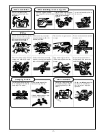
- To prevent the cut edges of tie wraps causing injury, do the following:
- Wind the tie wrap with its protruding part pointing downward (so that its cut end points downward).
- Cut off the excess tie wrap close to the head. Do not cut at an angle.
On GALANT without theft alarm system, the hood switch (Mitsubishi genuine part, sold separately) is also required.
Note
Содержание MZ360360EX
Страница 6: ... 6 ...
Страница 7: ... 7 ...
Страница 16: ... 16 ...
Страница 17: ... 17 ...
Страница 28: ... 28 ...
Страница 29: ... 29 ...
Страница 42: ... 42 Circuit Diagram ...
Страница 43: ... 43 ...
Страница 44: ... 44 Troubleshooting P 38 step 2 ...
Страница 45: ... 45 P 38 step 2 3 ...
Страница 46: ... 46 P 41 step 3 3 ...
Страница 47: ... 47 P 51 terminal No 3 P 51 ...
Страница 48: ... 48 P 51 P 51 terminal No 13 ...
Страница 49: ... 49 P 51 terminal No 24 P 51 terminal No 18 ...
Страница 50: ... 50 ...

