


APPENDIX
App. - 33
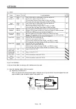
App. 5.11 Troubleshooting
When power is not supplied or FAULT LED turns on, refer the following table and take the appropriate
action.
Event Description
Cause
Action
Power is not supplied.
1. 24 V DC power supply is
malfunctioning.
Replace the 24 V DC power supply.
Power LED does not turn on
although power is supplied.
2. Wires between MR-J3-D05 and 24
V DC power supply are
disconnected or are in contact with
other wires.
Check the wiring.
3. MR-J3-D05 is malfunctioning.
Replace the MR-J3-D05.
FAULT LED is on.
1. The delay time settings are not
matched.
Check the settings of the rotary
switch.
FAULT LED of A-axis or B-
axis is on, and will not turn
off.
2. Switch input error
Check the wiring or sequence of the
input signals.
3. TOF signal error
Check the connection with the servo
amplifier.
4. MR-J3-D05 is malfunctioning.
Replace the MR-J3-D05.
Содержание MR-J4-100A
Страница 9: ...A 8 MEMO ...
Страница 61: ...1 FUNCTIONS AND CONFIGURATION 1 44 MEMO ...
Страница 67: ...2 INSTALLATION 2 6 MEMO ...
Страница 137: ...3 SIGNALS AND WIRING 3 70 MEMO ...
Страница 261: ...6 NORMAL GAIN ADJUSTMENT 6 24 MEMO ...
Страница 291: ...7 SPECIAL ADJUSTMENT FUNCTIONS 7 30 MEMO ...
Страница 299: ...8 TROUBLESHOOTING 8 8 MEMO ...
Страница 319: ...9 OUTLINE DRAWINGS 9 20 MEMO ...
Страница 461: ...12 ABSOLUTE POSITION DETECTION SYSTEM 12 36 MEMO ...
Страница 511: ...14 COMMUNICATION FUNCTION 14 38 MEMO ...
Страница 559: ...16 USING A DIRECT DRIVE MOTOR 16 20 MEMO ...
Страница 583: ...17 FULLY CLOSED LOOP SYSTEM 17 24 MEMO ...
Страница 621: ...APPENDIX App 38 ...
Страница 639: ......


