


5. PARAMETERS
5 - 48
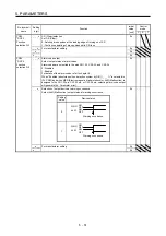
Control
mode
No./symbol/
name
Setting
digit
Function
Initial
value
[unit]
P S T
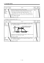
Any input device can be assigned to the CN1-17 pin.
When "_ _ _ 1" is set in [Pr. PA03] and absolute position detection system by DIO is selected, the CN1-17 pin will
become ABSM (ABS transfer mode).
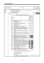
PD07
*DI3L
Input device
selection 3L
_ _ x x Position control mode - Device selection
Refer to table 5.9 in [Pr. PD03] for settings.
04h
x x _ _ Speed control mode - Device selection
Refer to table 5.9 in [Pr. PD03] for settings.
07h
Any input device can be assigned to the CN1-17 pin.
_ _ x x Torque control mode - Device selection
Refer to table 5.9 in [Pr. PD03] for settings.
07h
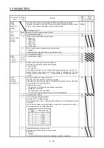
PD08
*DI3H
Input device
selection 3H
_ x _ _ For manufacturer setting
0h
x _ _ _
0h
Any input device can be assigned to the CN1-18 pin.
When "_ _ _ 1" is set in [Pr. PA03] and absolute position detection system by DIO is selected, the CN1-18 pin will
become ABSR (ABS transfer request).
PD09
*DI4L
Input device
selection 4L
_ _ x x Position control mode - Device selection
Refer to table 5.9 in [Pr. PD03] for settings.
05h
x x _ _ Speed control mode - Device selection
Refer to table 5.9 in [Pr. PD03] for settings.
08h
Any input device can be assigned to the CN1-18 pin.
_ _ x x Torque control mode - Device selection
Refer to table 5.9 in [Pr. PD03] for settings.
08h
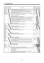
PD10
*DI4H
Input device
selection 4H
_ x _ _ For manufacturer setting
0h
x _ _ _
0h
Any input device can be assigned to the CN1-19 pin.
_ _ x x Position control mode - Device selection
Refer to table 5.9 in [Pr. PD03] for settings.
03h
PD11
*DI5L
Input device
selection 5L
x x _ _ Speed control mode - Device selection
Refer to table 5.9 in [Pr. PD03] for settings.
03h
Any input device can be assigned to the CN1-19 pin.
_ _ x x Torque control mode - Device selection
Refer to table 5.9 in [Pr. PD03] for settings.
03h
PD12
*DI5H
Input device
selection 5H
_ x _ _ For manufacturer setting
0h
x _ _ _
0h
Any input device can be assigned to the CN1-41 pin.
_ _ x x Position control mode - Device selection
Refer to table 5.9 in [Pr. PD03] for settings.
06h
PD13
*DI6L
Input device
selection 6L
x x _ _ Speed control mode - Device selection
Refer to table 5.9 in [Pr. PD03] for settings.
20h
Any input device can be assigned to the CN1-41 pin.
_ _ x x Torque control mode - Device selection
Refer to table 5.9 in [Pr. PD03] for settings.
20h
PD14
*DI6H
Input device
selection 6H
_ x _ _ For manufacturer setting
0h
x _ _ _
0h
Any input device can be assigned to the CN1-43 pin.
_ _ x x Position control mode - Device selection
Refer to table 5.9 in [Pr. PD03] for settings.
0Ah
PD17
*DI8L
Input device
selection 8L
x x _ _ Speed control mode - Device selection
Refer to table 5.9 in [Pr. PD03] for settings.
0Ah
Any input device can be assigned to the CN1-43 pin.
_ _ x x Torque control mode - Device selection
Refer to table 5.9 in [Pr. PD03] for settings.
00h
PD18
*DI8H
Input device
selection 8H
_ x _ _ For manufacturer setting
0h
x _ _ _
0h
Содержание MR-J4-100A
Страница 9: ...A 8 MEMO ...
Страница 61: ...1 FUNCTIONS AND CONFIGURATION 1 44 MEMO ...
Страница 67: ...2 INSTALLATION 2 6 MEMO ...
Страница 137: ...3 SIGNALS AND WIRING 3 70 MEMO ...
Страница 261: ...6 NORMAL GAIN ADJUSTMENT 6 24 MEMO ...
Страница 291: ...7 SPECIAL ADJUSTMENT FUNCTIONS 7 30 MEMO ...
Страница 299: ...8 TROUBLESHOOTING 8 8 MEMO ...
Страница 319: ...9 OUTLINE DRAWINGS 9 20 MEMO ...
Страница 461: ...12 ABSOLUTE POSITION DETECTION SYSTEM 12 36 MEMO ...
Страница 511: ...14 COMMUNICATION FUNCTION 14 38 MEMO ...
Страница 559: ...16 USING A DIRECT DRIVE MOTOR 16 20 MEMO ...
Страница 583: ...17 FULLY CLOSED LOOP SYSTEM 17 24 MEMO ...
Страница 621: ...APPENDIX App 38 ...
Страница 639: ......


