


1. FUNCTIONS AND CONFIGURATION
1 - 5
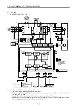
(c) MR-J4-11KA(-RJ)/MR-J4-15KA(-RJ)/MR-J4-22KA(-RJ)
U
U
U
L11
L21
N-
(Note 4)
C
L3
L2
L1
External dynamic
brake (optional)
MC
MCCB
U
V
W
U
V
W
P3
P+
+
+
B
RA
B1
B2
CN4
M
CN2
CN8
External regenerative
resistor or
regenerative option
CN5
CN3
CN6
I/F
USB
RS-422
D/A
A/D
USB
RS-422
CN1
CN2L
External encoder
(Note 3)
P4
Thyristor
(Note 5)
Model position
Current
control
Actual
position
control
Actual
speed
control
Virtual
motor
Virtual
encoder
Cooling fan
Encoder
(Note 2)
Power factor improving
DC reactor
Current
detection
Overcurrent
protection
Voltage
detection
(Note 1)
Power
supply
Base
amplifier
STO
circuit
Position
command
input
Servo amplifier
Diode
stack
24 V DC
Optional battery
(for absolute position
detection system)
STO
switch
Model speed Model torque
Control
circuit
power
Model
position
control
Model
speed
control
Servo motor
CHARGE
lamp
Regene-
rative
TR
Current
encoder
Analog monitor
(two channel)
Controller
Personal
computer
Analog
(two channel)
DI/O control
Servo-on
Input command pulse.
Start
Malfunction, etc
Step-
down
circuit
Electromagnetic
brake
Note 1. For the power supply specifications, refer to section 1.3.
2. The MR-J4 servo amplifier has P3 and P4 in the upstream of the inrush current suppression circuit. They are different from P1
and P2 of the MR-J3 servo amplifiers.
3. This is for the MR-J4-_A-RJ servo amplifier. The MR-J4-_A servo amplifier does not have the CN2L connector.
4. Use an external dynamic brake for this servo amplifier. Failure to do so will cause an accident because the servo motor dose
not stop immediately but coasts at an alarm occurrence for which the servo motor does not decelerate to stop. Ensure the
safety in the entire equipment. For alarms for which the servo motor does not decelerate to stop, refer to chapter 8.
5. The power factor improving AC reactor can also be used. In this case, the power factor improving DC reactor cannot be used.
When not using the power factor improving DC reactor, short P3 and P4.
Содержание MR-J4-100A
Страница 9: ...A 8 MEMO ...
Страница 61: ...1 FUNCTIONS AND CONFIGURATION 1 44 MEMO ...
Страница 67: ...2 INSTALLATION 2 6 MEMO ...
Страница 137: ...3 SIGNALS AND WIRING 3 70 MEMO ...
Страница 261: ...6 NORMAL GAIN ADJUSTMENT 6 24 MEMO ...
Страница 291: ...7 SPECIAL ADJUSTMENT FUNCTIONS 7 30 MEMO ...
Страница 299: ...8 TROUBLESHOOTING 8 8 MEMO ...
Страница 319: ...9 OUTLINE DRAWINGS 9 20 MEMO ...
Страница 461: ...12 ABSOLUTE POSITION DETECTION SYSTEM 12 36 MEMO ...
Страница 511: ...14 COMMUNICATION FUNCTION 14 38 MEMO ...
Страница 559: ...16 USING A DIRECT DRIVE MOTOR 16 20 MEMO ...
Страница 583: ...17 FULLY CLOSED LOOP SYSTEM 17 24 MEMO ...
Страница 621: ...APPENDIX App 38 ...
Страница 639: ......


