


1. FUNCTIONS AND CONFIGURATION
1 - 23
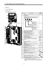
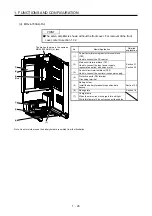
(2) 400 V class
(a) For MR-J4-200A4(-RJ) or less
The diagram is for MR-J4-60A4-RJ.
No. Name/Application
Detailed
explanation
(1)
Display
The 5-digit, seven-segment LED shows the servo
status and the alarm number.
(2)
Operation section
Used to perform status display, diagnostic, alarm,
and parameter setting operations. Push the
"MODE" and "SET" buttons at the same time for 3 s
or more to switch to the one-touch tuning mode.
Used to set data. Push
this button together with
the "MODE" button for
3 s or more to switch to
the one-touch tuning
mode.
MODE UP DOWN SET
Used to change the
display or data in each
mode.
Used to change the
mode. Push this button
together wish the "SET"
button for 3 s or more to
switch to the one-touch
tuning mode.
Section 4.5
(3)
USB communication connector (CN5)
Connect with the personal computer.
Section
11.7
(4)
Analog monitor connector (CN6)
Outputs the analog monitor.
Section 3.2
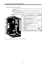
(5)
RS-422 communication connector (CN3)
Connect with the personal computer, etc.
Chapter 14
(6)
STO input signal connector (CN8)
Used to connect MR-J3-D05 safety logic unit and
external safety relay.
Chapter 13
App. 5
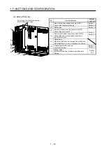
(7)
I/O signal connector (CN1)
Used to connect digital I/O signals.
Section 3.2
Section 3.4
(8)
(Note
2)
Encoder connector (CN2)
Used to connect the servo motor encoder or
external encoder. Refer to table 1.1 for the
compatible external encoders.
Section 3.4
"Servo
Motor
Instruction
Manual
(Vol. 3)"
(9)
Battery connector (CN4)
Used to connect the battery for absolute position
data backup.
Chapter 12
(10)
Battery holder
Install the battery for absolute position data backup.
Section
12.2
(11)
Protective earth (PE) terminal
Grounding terminal
(12)
Main circuit power supply connector (CNP1)
Connect the input power supply.
Section 3.1
Section 3.3
(13) Rating plate
Section 1.6
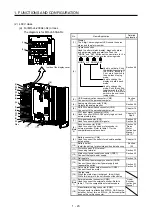
(14)
Control circuit power supply connector (CNP2)
Connect the control circuit power supply and
regenerative option.
(15)
Servo motor power output connector (CNP3)
Connect the servo motor.
Section 3.1
Section 3.3
(16)
Charge lamp
When the main circuit is charged, this will light.
While this lamp is lit, do not reconnect the cables.
(17)
(Note
1)
External encoder connector (CN2L)
Used to connect the external encoder. Refer to
table 1.1 for the compatible external encoders.
"Linear
Encoder
Instruction
Manual"
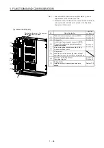
Inside of the display cover
MODE
UP
DOWN
SET
(1)
(3)
(4)
(12)
(14)
(13)
Side
(15)
(16)
(5)
(6)
(7)
(8)
(10)
(18)
(11)
(17)
(9)
(2)
(18)
Manufacturer setting connector (CN2L)
This connector is attached on MR-J4-_A4-RJ servo
amplifier, but not for use. MR-J4-_A4 servo amplifier
does not have this connector.
Содержание MR-J4-100A
Страница 9: ...A 8 MEMO ...
Страница 61: ...1 FUNCTIONS AND CONFIGURATION 1 44 MEMO ...
Страница 67: ...2 INSTALLATION 2 6 MEMO ...
Страница 137: ...3 SIGNALS AND WIRING 3 70 MEMO ...
Страница 261: ...6 NORMAL GAIN ADJUSTMENT 6 24 MEMO ...
Страница 291: ...7 SPECIAL ADJUSTMENT FUNCTIONS 7 30 MEMO ...
Страница 299: ...8 TROUBLESHOOTING 8 8 MEMO ...
Страница 319: ...9 OUTLINE DRAWINGS 9 20 MEMO ...
Страница 461: ...12 ABSOLUTE POSITION DETECTION SYSTEM 12 36 MEMO ...
Страница 511: ...14 COMMUNICATION FUNCTION 14 38 MEMO ...
Страница 559: ...16 USING A DIRECT DRIVE MOTOR 16 20 MEMO ...
Страница 583: ...17 FULLY CLOSED LOOP SYSTEM 17 24 MEMO ...
Страница 621: ...APPENDIX App 38 ...
Страница 639: ......


