


3. SIGNALS AND WIRING
3 - 65
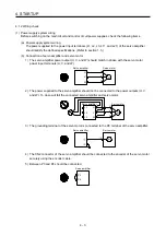
(2) Setting
(a) Enable MBR (Electromagnetic brake interlock) with [Pr. PD23] to [Pr. PD26] and [Pr. PD28].
(b) In [Pr. PC16 Electromagnetic brake sequence output], set a delay time (Tb) from MBR
(Electromagnetic brake interlock) off to base circuit shut-off at a servo-off as in the timing chart in
section 3.10.2 (1).
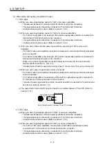
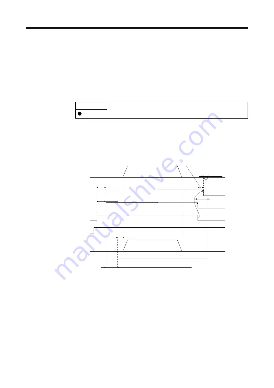
3.10.2 Timing chart
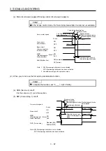
(1) When you use the forced stop deceleration function
POINT
To enable the function, set "2 _ _ _ (initial value)" in [Pr. PA04].
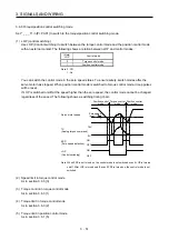
(a) SON (Servo-on) on/off
When SON (Servo-on) is turned off, the servo lock will be released after Tb [ms], and the servo
motor will coast. If the electromagnetic brake is enabled during servo-lock, the brake life may be
shorter. Therefore, set Tb about 1.5 times of the minimum delay time where the moving part will not
drop down for a vertical axis system, etc.
Approx. 95 ms
Approx. 95 ms
MBR
(Electromagnetic
brake interlock)
(Note 1)
ON
OFF
ON
OFF
0 r/min
Base circuit
Servo motor speed
Coasting
Operation delay time of
the electromagnetic brake
Ready-on command
(from controller)
ON
OFF
Release
Activate
Operation command
(from controller)
Electromagnetic
brake
Release delay time and external relay, etc. (Note 2)
(Note 3)
0 r/min
Servo-on command
(from controller)
ON
OFF
Tb [Pr. PC16 Electromagnetic brake sequence output]
Note 1. ON: Electromagnetic brake is not activated.
OFF: Electromagnetic brake has been activated.
2. Electromagnetic brake is released after delaying for the release delay time of electromagnetic brake and operation time of
external circuit relay. For the release delay time of electromagnetic brake, refer to "Servo Motor Instruction Manual (Vol. 3)".
3. Give a position command after the electromagnetic brake is released.
4. This is in position control mode.
Содержание MR-J4-100A
Страница 9: ...A 8 MEMO ...
Страница 61: ...1 FUNCTIONS AND CONFIGURATION 1 44 MEMO ...
Страница 67: ...2 INSTALLATION 2 6 MEMO ...
Страница 137: ...3 SIGNALS AND WIRING 3 70 MEMO ...
Страница 261: ...6 NORMAL GAIN ADJUSTMENT 6 24 MEMO ...
Страница 291: ...7 SPECIAL ADJUSTMENT FUNCTIONS 7 30 MEMO ...
Страница 299: ...8 TROUBLESHOOTING 8 8 MEMO ...
Страница 319: ...9 OUTLINE DRAWINGS 9 20 MEMO ...
Страница 461: ...12 ABSOLUTE POSITION DETECTION SYSTEM 12 36 MEMO ...
Страница 511: ...14 COMMUNICATION FUNCTION 14 38 MEMO ...
Страница 559: ...16 USING A DIRECT DRIVE MOTOR 16 20 MEMO ...
Страница 583: ...17 FULLY CLOSED LOOP SYSTEM 17 24 MEMO ...
Страница 621: ...APPENDIX App 38 ...
Страница 639: ......


