


3. SIGNALS AND WIRING
3 - 46
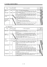
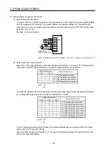
Normally, connect as follows.
Japan resistor
RRS10 or equivalent
SP2
DICOM
P15R
VLA
LG
SD
Servo amplifier
SP1
(Note)
2 k
Ω
2 k
Ω
24 V DC
Note. This diagram shows sink I/O interface. For source I/O interface, refer to section 3.9.3.
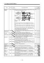
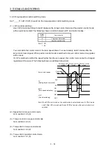
(b) Speed limit value selection
Select any of the speed settings by the internal speed limits 1 to 7 and by VLA (Analog speed limit)
using SP1 (Speed selection 1), SP2 (Speed selection 2), and SP3 (Speed selection 3) as follows.
(Note) Input device
SP3 SP2 SP1
Speed limit
0
0
0
VLA (Analog speed limit)
0
0
1
Pr. PC05 Internal speed limit 1
0
1
0
Pr. PC06 Internal speed limit 2
0
1
1
Pr. PC07 Internal speed limit 3
1
0
0
Pr. PC08 Internal speed limit 4
1
0
1
Pr. PC09 Internal speed limit 5
1
1
0
Pr. PC10 Internal speed limit 6
1
1
1
Pr. PC11 Internal speed limit 7
Note. 0: Off
1: On
When the internal speed limits 1 to 7 are used to limit a speed, the speed does not vary with the
ambient temperature.
(c) VLC (Limiting speed)
VLC turns on when the servo motor speed reaches a speed limited with internal speed limits 1 to 7
or analog speed limit.
Содержание MR-J4-100A
Страница 9: ...A 8 MEMO ...
Страница 61: ...1 FUNCTIONS AND CONFIGURATION 1 44 MEMO ...
Страница 67: ...2 INSTALLATION 2 6 MEMO ...
Страница 137: ...3 SIGNALS AND WIRING 3 70 MEMO ...
Страница 261: ...6 NORMAL GAIN ADJUSTMENT 6 24 MEMO ...
Страница 291: ...7 SPECIAL ADJUSTMENT FUNCTIONS 7 30 MEMO ...
Страница 299: ...8 TROUBLESHOOTING 8 8 MEMO ...
Страница 319: ...9 OUTLINE DRAWINGS 9 20 MEMO ...
Страница 461: ...12 ABSOLUTE POSITION DETECTION SYSTEM 12 36 MEMO ...
Страница 511: ...14 COMMUNICATION FUNCTION 14 38 MEMO ...
Страница 559: ...16 USING A DIRECT DRIVE MOTOR 16 20 MEMO ...
Страница 583: ...17 FULLY CLOSED LOOP SYSTEM 17 24 MEMO ...
Страница 621: ...APPENDIX App 38 ...
Страница 639: ......


