


3. SIGNALS AND WIRING
3 - 44
3.6.3 Torque control mode
(1) Torque limit
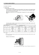
(a) Torque command and torque
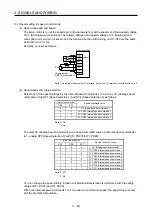
The following shows a relation between the applied voltage of TC (Analog torque command) and the
torque by the servo motor.
The maximum torque is generated at ±8 V. The speed at ±8 V can be changed with [Pr. PC13].
Forward rotation
(CCW)
Reverse rotation
(CW)
Maximum torque
Torque
CCW direction
TC applied voltage [V]
CW direction Maximum torque
-8
+8
-0.05
+0.05
Generated torque command values will vary about 5% relative to the voltage depending on products.
The torque may vary if the voltage is low (-0.05 V to 0.05 V) and the actual speed is close to the limit
value. In such a case, increase the speed limit value.
The following table indicates the torque generation directions determined by RS1 (Forward rotation
selection) and RS2 (Reverse rotation selection) when TC (Analog torque command) is used.
(Note) Input device
Rotation direction
TC (Analog torque command)
RS2 RS1
Polarity: +
0 V
Polarity: -
0
0
Torque is not generated.
Torque is not generated.
0 1
CCW
(Forward rotation in
power running
mode/reverse rotation in
regenerative mode)
CW
(Reverse rotation in
power running
mode/forward rotation in
regenerative mode)
1 0
CW
(Reverse rotation in
power running
mode/forward rotation in
regenerative mode)
CCW
(Forward rotation in
power running
mode/reverse rotation in
regenerative mode)
1
1
Torque is not generated.
Torque is not generated.
Torque is not generated.
Note. 0: Off
1: On
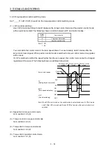
Normally, connect as follows.
RS2
24 V DC
DICOM
TC
LG
SD
RS1
-8 V to 8 V
Servo amplifier
(Note)
Note. This diagram shows sink I/O interface. For source I/O interface, refer to section 3.9.3.
Содержание MR-J4-100A
Страница 9: ...A 8 MEMO ...
Страница 61: ...1 FUNCTIONS AND CONFIGURATION 1 44 MEMO ...
Страница 67: ...2 INSTALLATION 2 6 MEMO ...
Страница 137: ...3 SIGNALS AND WIRING 3 70 MEMO ...
Страница 261: ...6 NORMAL GAIN ADJUSTMENT 6 24 MEMO ...
Страница 291: ...7 SPECIAL ADJUSTMENT FUNCTIONS 7 30 MEMO ...
Страница 299: ...8 TROUBLESHOOTING 8 8 MEMO ...
Страница 319: ...9 OUTLINE DRAWINGS 9 20 MEMO ...
Страница 461: ...12 ABSOLUTE POSITION DETECTION SYSTEM 12 36 MEMO ...
Страница 511: ...14 COMMUNICATION FUNCTION 14 38 MEMO ...
Страница 559: ...16 USING A DIRECT DRIVE MOTOR 16 20 MEMO ...
Страница 583: ...17 FULLY CLOSED LOOP SYSTEM 17 24 MEMO ...
Страница 621: ...APPENDIX App 38 ...
Страница 639: ......


