


OM-267043 Page 19
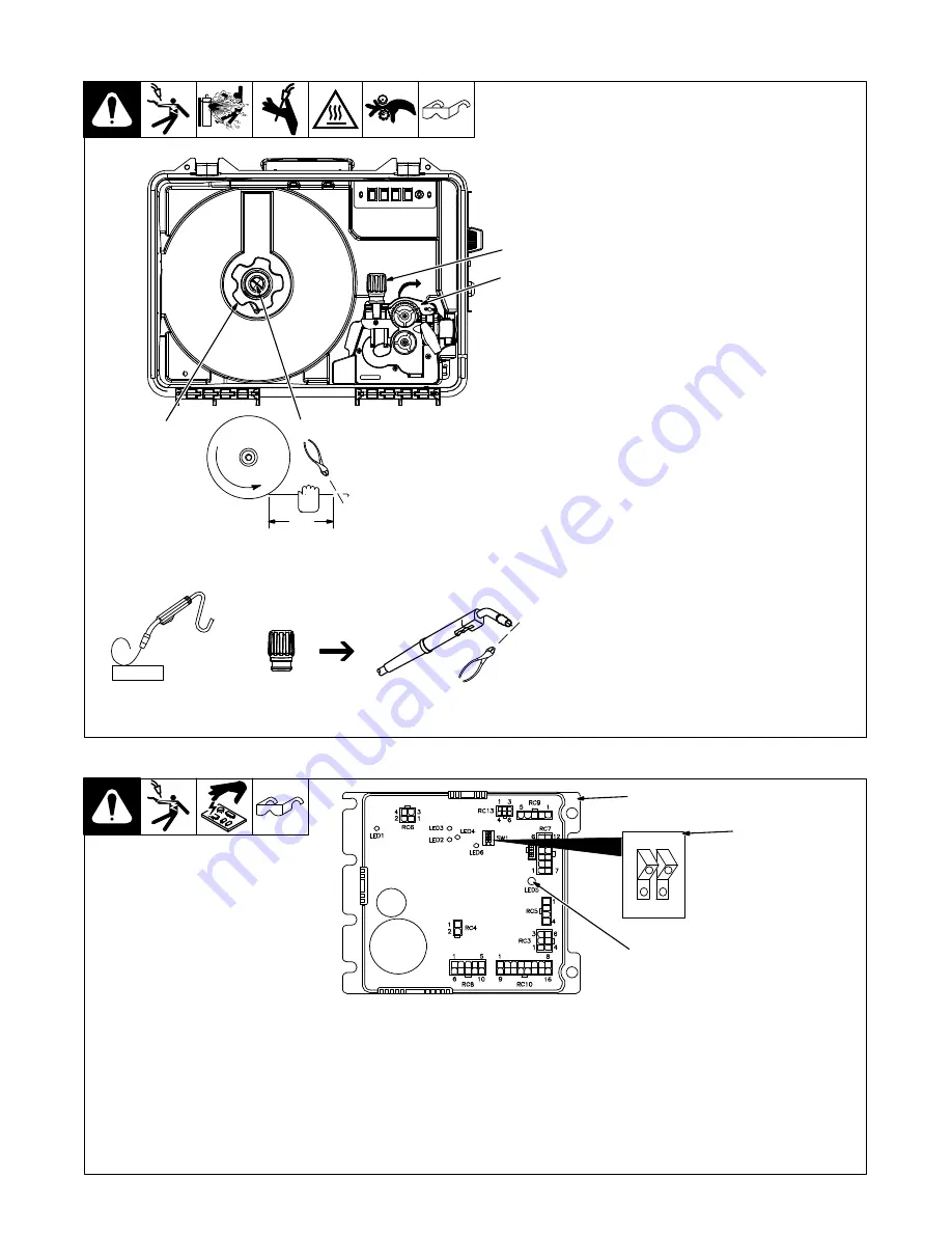
5-10. Installing And Threading Welding Wire
Ref. 257 806-B
Pull and hold wire; cut off end.
6 in.
(150 mm)
1
2
3
WOOD
.
Hold wire tightly
to keep it from
unraveling.
Tighten
Clockwise
Installing Wire And Adjusting Hub
Tension
1
Retaining Nut
2
Hub Tension Adjustment Knob
Remove retaining nut, and install spool
so hub pin fits spool hole. Reinstall re-
taining nut.
Adjust tension knob so only a slight force
is needed to turn spool.
.
Do not over tighten tension knob. It
is not necessary to use any tools to
tighten the knob.
Threading Welding Wire
3
Pressure Adjustment Knob
4
Pressure Assembly
Lay gun cable out straight.
Open pressure assembly. Hold wire
tightly and cut off end. Guide wire
between alignment pins, into drive roll
grooves, and into gun liner.
Close pressure assembly and tighten
pressure adjustment knob enough to
feed wire. Press jog switch until wire
comes out of gun.
To set proper drive roll pressure, release
the pressure on the drive rolls by loosen-
ing the pressure adjustment knob. Posi-
tion gun at about a 45 degree angle, with
nozzle about two inches from a wooden
surface. While feeding the wire against
the wooden surface, increase the pres-
sure to one half turn past the point where
the wire stops slipping. If the wire slips at
maximum hand-tight pressure, there
may be other problems. Check the gun
liner, spool tension, contact tip and drive
roll wear, as all these can cause wire
feeding problems.
Cut off wire, and close door.
4
5-11. Motor Board (PC1) DIP Switch Settings
247 678-B
1
Motor Control Board PC1
2
DIP Switch SW1
3
LED5
.
DIP switch SW1 is used to match the
performance of PC1 to the character-
istics of the motor used in the feeder.
Setting SW1 as shown will help insure
that PC1 and motor are matched for
optimal performance.
Set switch positions 1 and 2 so the de-
pressed section of both tabs are toward 1
and 2 as labeled on the switch. As shown
in illustration.
When feeder is powered up, LED 5 on the
motor control board will blink four times.
This blinking indicates everything is work-
ing properly and the DIP switch is set cor-
rectly.
After LED 5 is done blinking, it will be either
red or green. Red indicates that the feeder
is connected with electrode positive.
Green indicates feeder is connected with
electrode negative.
1
2
OP
EN
RC111
1
2
3
Содержание FieldPro Feeder CE
Страница 4: ......
Страница 6: ......
Страница 35: ...OM 267043 Page 29 SECTION 8 ELECTRICAL DIAGRAM 257 274 C Figure 8 1 Circuit Diagram For Wire Feeder...


