background image


Technical Information 


27 

H 408x BM 

moisture will build up in the oven cavity. 

b. 

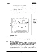
Air path during convection, broil and combination cycles: 

The air 

baffle (Figure 012-1, Item 5) remains closed. Vapors move through 
the vapor passage (Figure 012-1, Item 6) into the vent (Figure 012-1, 
Item 7) and mix with cool air. 

3. 

Cool air and vapor exit: 

Cool air and vapor are pushed out through the vent above the air guide at 
the front of the appliance. 


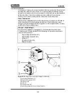
Figure 012-1: 

Ducting


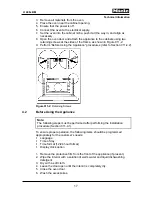
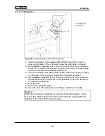
2.2 Fan 

Cooldown 

The cooldown function protects the appliance from damage by temperature 
and moisture. It is switched off when the oven cavity temperature falls below 
167°F (75°C). 


2.3 Microwave 

Operation


The high-voltage system generates the microwave energy. The incoming AC 
power passes through a “step-up” transformer and is further increased by the 
diode-rectifier circuit (including a high-voltage capacitor) to supply the 
magnetron with high-voltage DC power. The magnetron converts this high-
voltage DC to microwaves. The microwaves pass through the wave guide and 
are dispersed into the oven cavity by the wave distributor motor. The oven 
cavity is designed to resonate the microwaves that are absorbed by the food.  

1

 Cooling fan 

2

 Rear air duct 

3

 Front air duct 

4

 Release element 

5

 Air baffle 

6

 Vapor passage 

7

 Vent 

Содержание H 4080 BM

Страница 1: ...TECHNICAL INFORMATION H 408x BM Speed Ovens 2013 Miele USA ...

Страница 2: ...18 4 4 Outer Side Cover Removal 18 4 5 Side Panel Removal 18 4 6 Removing the Door Lock Torsion Spring 18 4 7 Door Latch Removal 19 4 8 Door Lock Removal 20 4 9 Door Switch Adjustment 21 012 Air Duct Magnetron 25 1 Technical Data 26 2 Function 26 2 1 Air and Vapor Ducting 26 2 2 Fan Cooldown 27 2 3 Microwave Operation 27 4 Service 29 4 1 Front Air Duct Removal up to Machine No 10 59114003 29 4 2 R...

Страница 3: ...48 4 2 Halogen Lamp Removal 50 4 3 Measuring the Temperature in the Middle of the Oven Cavity 50 032 Convection Fan Heaters 52 1 Technical Data 53 2 Function 53 2 1 Safety Cutoff 53 2 2 Heater Element Timing 53 2 3 Heater Element Switching in Operating Modes 54 2 4 Convection Fan 54 4 Service 54 4 1 Fan Impeller Removal 54 4 2 Convection Fan M2 2 Removal 55 4 3 Removing Convection Heater Element R...

Страница 4: ... H 4080 BM 71 4 2 Programming Mode Overview H 4082 4 6 8 BM 73 4 3 Service Mode Overview H 4080 BM 75 4 4 Service Mode Overview H 4082 4 6 8 BM 77 4 5 Reading and Deleting the Fault Memory 79 4 6 Fascia Panel Removal 79 4 7 Removing the Fascia Panel with Support Plate 80 4 8 Support Plate Removal 81 4 9 Power Electronic Removal 81 080 Technical Service Bulletins 82 1 H4XXX Cooling Fan Behavior 82 ...

Страница 5: ...ature of 20 C 68 F 51 Figure 032 1 Convection Plus Auto Roast 54 Figure 032 2 Broil Convection Broil 54 Figure 032 3 Microwave 54 Figure 032 4 Microwave Convection Plus Microwave Auto Roast Sequential Operation 54 Figure 032 5 Microwave Broil Microwave Convection Broil Sequential Operation 54 Figure 032 6 Fan Impeller Removal 55 Figure 032 7 Broil Heater Element Removal 57 Figure 040 1 Navitronic ...

Страница 6: ...m the power supply Service and repair work should only be carried out by qualified persons in accordance with all appropriate local and national safety regulations When carrying out measurements on an electronic connected to the power supply always use narrow measuring probes Contacts are very closely spaced and using thicker probes may cause short circuits 2 Discharging the High Voltage Capacitor...

Страница 7: ...n must never be operated without a microwave load Never look into an open waveguide or antenna when the appliance is on In order to ensure that no microwave energy can escape after any repair work has been completed the appliance must be thoroughly checked for microwave leaks in accordance with all applicable local and national regulations In Germany VDE regulation 0700 and CEE regulation 335 appl...

Страница 8: ...n the interlock monitor door seal and microwave generation and transmission systems shall be repaired replaced or adjusted by procedures described in this manual before the oven is released to the owner A microwave leakage test to verify compliance with national performance standards should be performed on each oven prior to release to the owner B Modification History When Who What 4 2 2013 Jessic...

Страница 9: ...W x D 18 1 x 15 4 Levels in cavity for racks 3 Supervision compatible No Yes Accessories included Roast probe Halogen lamp power rating 10W Controls Navitronic standard text display with touchpad controls Yes Time display Clock back up Yes Yes Delay start Cooking time End Yes Yes Yes Minute minders 2 MW recommended output Yes Recommended temperature Yes Actual temperature indication Yes not during...

Страница 10: ...onvection bake plus Microwave and convection bake times have to be set the same MW Broil Microwave and broil times have to be set the same MW Convection broil Microwave broil and convection fan times have to be set the same Masterchef programs Yes Favorites Yes Sabbath mode Yes Safety Automatic shutoff Yes Safety shutoff Yes System lock while running when not running No Yes Tip protection Slide ou...

Страница 11: ...formation 11 H 408x BM D Component Layouts 1 Appliance Overview Figure D 1 Overview of Appliance Front View 1 Control panel 2 Upper heating element broiler 3 Light 4 Roast probe socket 5 Level runners 3 6 Oven door ...

Страница 12: ...w of Controls Figure D 2 Overview of Controls H 4082 BM Shown 1 Menu touchpads 2 Numeric touchpads 3 On Off touchpad 4 Minute touchpad 5 Display 6 Clear touchpad 7 Timer touchpad Note The Clear and Timer touchpads are switched on H 4080 BM models ...

Страница 13: ...6 6 5F6 6 Left door lock with 3 safety switches 22 A4 High voltage capacitor 23 Y56 Release element 7 2T1 Lighting transformer 24 3F6 6 4F6 6 Right door lock with 2 safety switches 8 2F1 1 Thermostat Fan Heat safety cutoff 248 F 25 1A1 Control electronic EPX 26 2A1 Selection electronic EW 9 Z1 Interference suppression filter 27 1H3 2 Oven cavity light 10 X5 X10 1 RemoteVision socket 28 X5 8 Socket...

Страница 14: ...30 Oven temperature sensor PT1000 19 Y56 Release element 20 3F6 6 4F6 6 Right door lock with 2 safety switches 6 R15 Broiler 7 1F6 6 2F6 6 5F6 6 Left door lock with 3 safety switches 21 1A1 Control electronic EPX 22 2A1 Selection electronic EW 8 2T1 Lighting transformer 23 1H3 2 Oven cavity light 9 Z2 Interference suppression capacitor 24 2R30 Roast probe temperature sensor 10 M2 1 Cooling fan Not...

Страница 15: ...Technical Information 15 H 408x BM 011 Casing Door Lock ...

Страница 16: ...hot even though they are not glowing Note To avoid preventable damage to the appliance follow the handling instructions attached to the top of the appliance as shown in Figure 011 1 Figure 011 1 Handling Instructions Sheet Shipped with Appliance 1 Ensure that the supports and the opening in the cabinet allow for proper installation 2 Ensure that the electrical supply meets the appliance requiremen...

Страница 17: ...dures refer to Section 011 4 2 Figure 011 2 Retaining Screws 4 2 Before Using the Appliance Note The following steps must be performed after performing the installation procedure Section 011 4 1 To ensure proper operation the following items should be programmed appropriately for the customer s needs Language Time of day Time format 12 24 hour format Display clock option 1 Remove the protective fi...

Страница 18: ...cabinet 5 Disconnect the power cable 4 4 Outer Side Cover Removal 1 Remove the appliance from its cabinet see Section 011 4 3 2 Remove the four T20 screws securing each side cover Remove the side covers 4 5 Side Panel Removal 1 Remove the appliance from its cabinet see Section 011 4 3 2 Remove the outer side covers See Section 011 4 4 3 Remove the five T20 screws securing the left side panel 3 on ...

Страница 19: ...oor and the housing edges 4 7 Door Latch Removal 1 Remove the appliance from its cabinet see Section 011 4 3 2 Remove the screws securing the appliance lid Remove the lid Danger Before performing any service or repair work discharge the high voltage capacitor See Section A 2 3 Remove the fascia panel with support plate See Section 040 4 7 4 Remove the door safety switches door lock see Section 011...

Страница 20: ...5 Wire Bracket and Hooks Danger After installing the door lock adjust the door switches See Section 011 4 9 After installation is completed as a matter of standard practice check the oven for a tight seal with a microwave leak detector paying particular attention to the door and the housing edges 4 8 Door Lock Removal 1 Remove the appliance from its cabinet see Section 011 4 3 2 Remove the screws ...

Страница 21: ... function of the safety switches the door switches have to be adjusted again after work on the door lock is completed Two door locks are located behind the control panel at the left and right with a total of five safety switches Each door lock is equipped with a standard safety switch 1F6 6 left Figure 011 8 Item 1 and 3F6 6 right Figure 011 8 Item 3 and switched behind it a monitor switch 2F6 6 l...

Страница 22: ...ge is within the permissible limits For this procedure the complete door lock assembly must be installed The appliance must be disconnected from power Required parts 3 blue magnetic shim strips 1 x 2 8 x 0 03 mat no 05055650 3 brown magnetic shim strips 1 x 2 8 x 0 06 mat no 05057340 1 Remove the appliance from its cabinet see Section 011 4 3 2 Remove the screws securing the appliance lid Remove t...

Страница 23: ...hnical Information 23 H 408x BM Figure 011 7 Magnetic Strips Figure 011 8 Door Safety Switches 1 Safety switch 1F6 6 2 Safety switch 2F6 6 3 Safety switch 3F6 6 4 Safety switch 4F6 6 5 Safety switch 5F6 6 ...

Страница 24: ...inuity of left safety switch 1F6 6 Figure 011 8 Item 1 using an ohmmeter If the ohmmeter beeps then the switch is closed 12 Use a metric 8 millimeter socket wrench to turn the set screw clockwise until the switch opens ohmmeter no longer beeps Then turn the switch an additional quarter turn 13 Open the door 14 Remove the magnetic strips 15 Close the door The ohmmeter should beep indicating continu...

Страница 25: ...Technical Information 25 H 408x BM 012 Air Duct Magnetron ...

Страница 26: ...The incoming air cools the appliance the electrical components and the surrounding cabinet on all sides 2 Cool air and vapor path The fan moves the cool air to the rear of the air duct Figure 012 1 Item 2 The air cools the magnetron and is then moved through the front of the air duct Figure 012 1 Item 3 where it exits the appliance Since machine no 10 59114004 the multi piece metal ducting has bee...

Страница 27: ...rature and moisture It is switched off when the oven cavity temperature falls below 167 F 75 C 2 3 Microwave Operation The high voltage system generates the microwave energy The incoming AC power passes through a step up transformer and is further increased by the diode rectifier circuit including a high voltage capacitor to supply the magnetron with high voltage DC power The magnetron converts th...

Страница 28: ... on off ratio of current provided to the high voltage transformer The transformer output changes cycle accordingly and the magnetron is then supplied with a varying on off cycle of high voltage power Danger High Voltage Even with the appliance unplugged i e circuit breaker shut off high voltage power remains present at the following components and poses a risk of electrical shock High voltage tran...

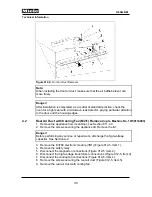
Страница 29: ...Danger Before performing any service or repair work discharge the high voltage capacitor See Section A 2 3 Remove the fascia panel See Section 040 4 5 4 Remove the door spring See Section 011 4 6 5 Remove the support plate See Section 040 4 7 6 Remove the screws securing the release element Figure 012 4 Item 1 7 Remove the release element Figure 012 4 Item 2 8 Remove the screws securing the air du...

Страница 30: ...10 59114003 1 Remove the appliance from its cabinet see Section 011 4 3 2 Remove the screws securing the appliance lid Remove the lid Danger Before performing any service or repair work discharge the high voltage capacitor See Section A 2 3 Remove the EV790 electronic module 3N1 Figure 012 5 Item 1 4 Remove the safety relay 5 Disconnect the magnetron connections Figure 012 5 Item 2 6 Disconnect th...

Страница 31: ...ring the appliance lid Remove the lid Danger Before performing any service or repair work discharge the high voltage capacitor See Section A 2 3 Remove the fascia panel with support plate See Section 040 4 6 4 Disconnect the magnetron thermostat connections Figure 012 6 Item 1 5 Remove the screws securing the magnetron thermostat Figure 012 6 Item 2 6 Remove the magnetron thermostat Figure 012 6 I...

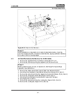
Страница 32: ...the electrical connections to all components on the ducting 14 Remove the air duct Figure 012 7 Item 3 Figure 012 7 Air Duct Removal Step 2 Note When installing the air duct make sure that the air baffle below it can move freely Danger After installation is completed as a matter of standard practice check the oven for a tight seal with a microwave leak detector paying particular attention to the d...

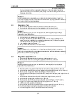
Страница 33: ...andard practice check the oven for a tight seal with a microwave leak detector paying particular attention to the door and the housing edges 4 5 Cooling Fan M2 1 Removal up to Machine No 10 59114003 1 Remove the appliance from its cabinet see Section 011 4 3 2 Remove the screws securing the appliance lid Remove the lid Danger Before performing any service or repair work discharge the high voltage ...

Страница 34: ...2 9 Item 2 5 Remove the cooling fan Figure 012 9 Cooling Fan Removal Danger After installation is completed as a matter of standard practice check the oven for a tight seal with a microwave leak detector paying particular attention to the door and the housing edges 4 7 Testing the Magnetron G2 Filament 1 Remove the appliance from its cabinet see Section 011 4 3 2 Remove the screws securing the app...

Страница 35: ... a matter of standard practice check the oven for a tight seal with a microwave leak detector paying particular attention to the door and the housing edges 4 9 Magnetron G2 Removal 1 Remove the appliance from its cabinet see Section 011 4 3 2 Remove the screws securing the appliance lid Remove the lid Danger Before performing any service or repair work discharge the high voltage capacitor See Sect...

Страница 36: ...icular attention to the door and the housing edges 4 10 Removing High Voltage Capacitor A4 1 Remove the appliance from its cabinet see Section 011 4 3 2 Remove the screws securing the appliance lid Remove the lid Danger Before performing any service or repair work discharge the high voltage capacitor See Section A 2 3 Remove the capacitor retaining screw 4 Remove the capacitor from the clasp assem...

Страница 37: ...tir the water 8 Use a thermometer to measure the final water temperature TE 9 If the increase in temperature TE TA is at least 110 F or 120 F the microwave output is in order 4 12 High Voltage Transformer Test 1 Remove the appliance from its cabinet see Section 011 4 3 2 Remove the screws securing the appliance lid Remove the lid Danger Before performing any service or repair work discharge the hi...

Страница 38: ...practice the appliance has to be checked for a tight seal with a microwave leak detector paying particular attention to the door and the housing edges 4 14 High Voltage Capacitor Test 1 Remove the appliance from its cabinet see Section 011 4 3 2 Remove the screws securing the appliance lid Remove the lid Danger Before performing any service or repair work discharge the high voltage capacitor See S...

Страница 39: ...011 4 3 2 Remove the screws securing the appliance lid Remove the lid Danger Before performing any service or repair work discharge the high voltage capacitor See Section A 2 3 Remove the diode assembly from the appliance 4 Connect the V1 diode in series on the positive lead between a 9 volt battery and a voltmeter as shown in Figure 012 12 Item A A properly functioning diode should provide a volt...

Страница 40: ...microwave function is not working but other aspects of the appliance are in functioning order This procedure will quickly isolate the fault to the appropriate circuit and or component s Caution Parts of this procedure are performed while the appliance is connected to live power Do NOT deviate from this procedure or skip steps unless instructed to within the procedure Skipping steps can produce inc...

Страница 41: ... NOT present proceed to step 3 below 2 Check for 240VAC between ST6 pin 10 on the power electronic and the output double blue wire on the magnetron thermostat F1 2 a If 240VAC is present proceed to Section 4 18 3 b If 240VAC is NOT present replace F1 2 magnetron thermostat 3 Check for 240VAC between ST6 pin 10 on the power electronic 1N1 and L2 on the terminal block X3 1 a If 240VAC is present fau...

Страница 42: ... diode test Section 012 4 17 11 Reassemble the appliance 12 Access the oven cavity remove the ceiling cover retaining screws and ceiling cover 13 Restore power to the appliance 14 Briefly perform the microwave output test Section 012 4 11 and verify that the wave distributor motor is functioning turning 15 If all components test s check okay perform the following a Disconnect the appliance from po...

Страница 43: ...Technical Information 43 H 408x BM 020 Door ...

Страница 44: ...attention to the correct placement at the corners 4 2 Removing the Door Outer and Middle Panes 1 Open the door a few inches 2 Using a pointed tool push in the two silver notches on the door s upper edge until you hear it click Figure 020 1 Item 1 3 Tilt the outer pane a few inches forward pulling the pins of the door contact switches from their slots Figure 020 1 Item 2 Figure 020 1 Door Pane Remo...

Страница 45: ...efer to Section 020 4 2 2 Place the outer pane flat onto a work surface inner side facing up 3 Remove the handle retaining screws 4 Remove the handle 4 4 Removing the Door Inner Pane Note The door inner pane is not replaceable on its own If it is broken then the entire door must be replaced See Section 020 4 5 4 5 Removing the Door Complete with Hinges 1 Remove the appliance from its cabinet refer...

Страница 46: ...al Danger When installing the hinges place 3 blue magnetic strips 1 x 2 8 x 0 03 mat no 05055650 as spacers along the lower oven cavity edge Figure 011 7 Item 2 After re installation adjust the door switches see Section 011 4 9 After installation is completed as a matter of standard practice check the oven for a tight seal with a microwave leak detector paying particular attention to the door and ...

Страница 47: ...Technical Information 47 H 408x BM 031 Oven Cavity Wave Distribution ...

Страница 48: ...fectClean shine differently when exposed to light Remedy None 4 Service 4 1 Removing Wave Distributor Motor M21 1 Remove the appliance from its cabinet refer to Section 011 4 3 2 Open the door 3 Remove the thumbnut securing the broil element in the oven cavity 4 Flip down the broil element in the oven cavity 5 Remove the three T20 screws securing the ceiling cover Figure 031 1 Item 1 6 Remove the ...

Страница 49: ... the high voltage capacitor See Section A 2 9 Disconnect the motor connections Figure 031 1 Item 4 10 Remove the two T20 screws securing the motor Figure 031 1 Item 5 11 Remove the motor Figure 031 1 Item 6 Danger After installation is completed as a matter of standard practice check the oven for a tight seal with a microwave leak detector paying particular attention to the door and the housing ed...

Страница 50: ...ator is possible The specified times were obtained with a supply voltage of 230 volts Temperature variations were originally specified in K Kelvin Note Required tools Electronic thermometer mat no 05595760 Sensor mat no 07121370 Magnetic holder mat no 05054650 Sensor socket mat no 07132940 Oven rack 1 Check the voltage of the switched off and switched on heating system 2 Hook the sensor Figure 031...

Страница 51: ...or 2 Sensor socket 3 Magnetic holder X Distance from oven cavity floor 4 10 cm Y Distance from sensor tip to insertion greater than 2 5 cm Figure 031 3 Sample Measurement with an Ambient Temperature of 20 C 68 F X axis Time in minutes seconds Y axis Temperature in Celcius ...

Страница 52: ...Technical Information 52 H 408x BM 032 Convection Fan Heaters ...

Страница 53: ...heater elements and the magnetron are switched off via relay K1 Thermostat 1F1 1 275 F at the magnetron wave guide monitors the oven cavity temperature At excess temperatures safety relay K1 is activated which switches off both heaters Because of the distance to broil heater R15 the cutoff temperature is set correspondingly low If convection fan M2 2 is defective the safety cutoff of convection he...

Страница 54: ...ume of air in the small cavity located within the rear wall of the appliance to produce true convection heating 4 Service 4 1 Fan Impeller Removal 1 Remove the appliance from its cabinet refer to Section 011 4 3 2 Remove the three T20 screws securing the back wall as well as the T20 screw securing the terminal block cover Remove the terminal block cover and the back wall 3 Disconnect the connectio...

Страница 55: ...e 032 6 Fan Impeller Removal Note After installation of the fan rear panel replace the bottom insulation strip Danger After installation is completed as a matter of standard practice check the oven for a tight seal with a microwave leak detector paying particular attention to the door and the housing edges 4 2 Convection Fan M2 2 Removal 1 Remove the appliance from its cabinet refer to Section 011...

Страница 56: ...the bottom insulation strip 6 Remove the four T20 screws securing the bottom of the fan rear panel Figure 032 6 Item 4 7 Remove the fan rear panel with convection fan and convection heater 8 Unscrew the heater element retaining nuts 9 Remove the convection heater element Note After installation of the fan rear panel replace the bottom insulation strip Danger After installation is completed as a ma...

Страница 57: ...r and gently twist it out to remove 7 Pull the connectors off the heater element Figure 032 7 Item 1 8 Unscrew the two heater element locknuts Figure 032 7 Item 2 9 Remove the two support plates Figure 032 7 Item 3 10 Unscrew the thumbnut in the oven cavity Figure 032 7 Item 4 11 Take the heater element out of the oven cavity Figure 032 7 Item 5 Figure 032 7 Broil Heater Element Removal Danger Aft...

Страница 58: ...Technical Information 58 H 408x BM 040 Control Panel Electrical System ...

Страница 59: ...chpads respond to finger contact and each contact is confirmed by a tone This confirmation tone can be turned on or off in the customer programming mode Note The Navitronic display shown in Figure 040 1 is for an H 4080 BM On an H 4082 BM the Clear and Timer touchpads Items 4 and 5 are switched The four touchpads located in a horizontal line below the display are allocated to fixed functions The t...

Страница 60: ...ed such as cooking time or temperature the numeric keypad next to the display lights up Then and only then can a selection be made by touching the numerical fields Touching the pad next to OK confirms a selection or input The display will then revert to the previous menu 2 1 3 Optical Interface Figure 040 2 Optical Interface The appliance has an optical interface to support diagnostics and program...

Страница 61: ...Technical Information 61 H 408x BM 2 2 Connectors on Power Electronic EPL 1N1 H 4080 BM Only Note Plug and pin designations are the same as in the wiring diagram Figure 040 3 Power Electronic H 4080 BM ...

Страница 62: ...nt 3 6 Convection fan M2 2 3 7 Oven light transformer 2T1 3 8 vacant 3 9 Bridge to 6 1 ST5 Plug 5 5 1 Roast probe socket X5 8 5 2 Roast probe socket X5 8 ST6 Plug 6 6 1 Electronic EV 3N1 bridge to 3 9 6 2 vacant 6 3 Convection heater element R14 6 4 vacant 6 5 Broil heater element R15 6 6 vacant 6 7 Electronic 3N1 6 8 vacant 6 9 vacant 6 10 Door contact switch 4F6 6 6 11 Wave distributor motor M21...

Страница 63: ... 1 11 2 Cooling fan M2 1 11 3 Cooling fan M2 1 11 4 vacant 11 5 vacant 11 6 vacant 11 7 vacant ST12 Plug 12 12 1 12 10 Control electronic 2N1 ST13 Plug 13 13 1 Door contact safety switch F5 6 6 13 2 Door contact safety switch F5 6 6 Table 040 1 Power Electronic Connections H 4080 BM 2 3 Connectors on Power Electronic ELP 1N1 H 4082 4 6 8 BM Note Plug and pin designations are the same as in the wir...

Страница 64: ...is ground 1 4 L1 on terminal block bridge to 4 11 1 5 Door interlock primary switch left side F 6 6 4 ST2 Plug 2 2 1 Cooling fan M2 1 connection 2 RPM N1 low speed 2 2 Cooling fan M2 1 connection neutral 2 3 Cooling fan M2 1 connection 1 RPM N2 high speed 2 4 Release element Y56 2 5 Convection fan M2 2 2 6 vacant 2 7 Oven light transformer 2T1 2 8 vacant 2 9 Bridge to 4 10 ...

Страница 65: ...t R12 4 10 Bridge to 2 9 and 4 11 4 11 Bridge to 4 10 and 1 4 ST5 Plug 5 5 1 PT1000 temperature sensor 1R30 5 2 vacant 5 3 PT1000 temperature sensor 1R30 ST6 Plug 6 6 1 Thermostat oven cavity 275 F 1F1 6 2 vacant 6 3 vacant 6 4 Thermostat oven cavity 275 F 1F1 ST7 Plug 7 7 1 7 10 Control electronic 2N1 ST8 Plug 8 8 1 Door switch S24 8 2 Door switch S24 ST9 Plug 9 9 1 Cooling fan M2 1 9 2 Cooling f...

Страница 66: ...t circuited Remedy 1 Check all connectors 2 Replace connectors as necessary 3 Check the oven temperature sensor in service mode see Section 040 4 3 4 Replace the temperature sensor as necessary 3 3 F06 Open Circuit Oven Temperature Sensor Cause Oven temperature sensor 1R30 open circuited Remedy 1 Check all connectors 2 Replace connectors as necessary 3 Check the oven temperature sensor in service ...

Страница 67: ...lly Cause The appliance was not switched off Remedy No action necessary the appliance is in working order 3 7 F60 Temperature of Power Electronic Too High Symptom The temperature of the power electronic 1N1 is too high Cause Insufficient ducting Remedy 1 Check the ducting refer to Section 012 2 1 2 Check the cooling fan connectors replace as necessary 3 Check the cooling fan in service mode see Se...

Страница 68: ...tart can be programmed as automatic or manual If start was set to manual then the start of a cooking process must be confirmed manually Remedy Set start to automatic 3 13 Recommended Temperatures Are Changed Cause The recommended temperatures can be programmed Remedy See Section 040 4 1 3 14 Display Dims Cause The display can be programmed Remedy See Section 040 4 1 3 15 Display Is Too Bright Too ...

Страница 69: ...o accept or not accept the system lock can be programmed Remedy See Section 040 4 1 3 19 Weight in Pounds Cause Weight units can be programmed Remedy See Section 040 4 1 3 20 Temperature in C F Cause The temperature format can be programmed Remedy See Section 040 4 1 3 21 Appliance Does Not Heat Cause Demo mode is activated Remedy Deactivate the demo mode Not applicable in all models 3 22 Fuse Tri...

Страница 70: ... 012 4 16 d Protective diode V6 Section 012 4 17 e Magnetron Section 012 4 8 2 Replace the fuse Note Use only an original Miele microfuse which has special release characteristics Using other brands can cause malfunctions Note 12 amp fuses were used in the current production run If the fuse in the appliance is a 10 amp fuse it can be replaced with a 12 amp one if when it trips 3 23 Roast Probe Sho...

Страница 71: ...ppliance off Accessing Note Complete the access procedure within 10 seconds 1 Touch and hold the Clear pad 2 Touch the On Off pad 3 Release the Clear pad 4 Touch the Clear pad 5 times and on the 5th time hold it until the programming mode appears Acknowledgement indicator The display shows the following items of PROGRAMMING LANGUAGE CLOCK TEMPERATURE OVEN LIGHT TEMPERATURE F more Options Touch the...

Страница 72: ...00 to 400 F 400 F AUTO ROAST 200 to 425 F 325 F DEFROST 75 to 125 F 75 F OVEN LIGHT Off after 1 minute Off after 1 minute On during use TEMPERATURE F C C F F TONE OPTIONS Timer 1 Tone 1 5 1 Timer 2 Tone 1 5 1 Keypad Tone On On Off Volume 1 5 2 Tone Short Short Long DISPLAY Brightness 1 5 3 Contrast 1 5 3 SYSTEM LOCK Do not accept Do not accept Accept KEEP WARM On Off Off POWER LEVEL Microwave 7 le...

Страница 73: ...to the previous menu Save and quit Touch the pad next to OK Touch the On Off pad Quit without saving Touch the On Off pad 4 2 Programming Mode Overview H 4082 4 6 8 BM Initial requirements Switch the appliance off Accessing Note Complete the access procedure within 10 seconds 1 Touch and hold the Timer pad 2 Touch the On Off pad 3 Release the Timer pad 4 Touch the Timer pad 5 times and on the 5th ...

Страница 74: ...LOCK Size Normal Normal Large 12 hour format 12 hour format 24 hour format Clock Display On On Off ENTER TIME hh mm TEMPERATURES BAKE 200 to 475 F 375 F SURROUND 125 to 475 F 375 F INTENSIVE 200 to 475 F 325 F CONVECTION BAKE 125 to 435 F 325 F CONVECTION BROIL 200 to 400 F 400 F AUTO ROAST 200 to 425 F 325 F CONVECTION ROAST 200 to 475 F 325 F SURROUND ROAST 125 to 475 F 325 F OVEN LIGHT Off afte...

Страница 75: ...208V 208V 240V Table 040 5 H 4082 4 6 8 BM Programming Mode 1 Available languages will depend on the installed electronic version To go back Touch the Clear pad The display reverts to the previous menu Save and go back Confirm by touching the pad next to OK The selected setting is saved The display reverts to the previous menu Save and quit Touch the pad next to OK Touch the On Off pad Quit withou...

Страница 76: ...EST SENSOR TEST RUNNING TIME Options Touch the pad next to the desired function refer to Table 040 6 Service Function Option INDEX CONTROL EPX e g ID000853 POWER EPL e g ID000793 FAULT INDEX No faults Faults stored Fault 01 Fault 02 Clear faults FUNCTION TEST ALL OFF All previously activated components will be shut off BROILING On Off CONVECTION On Off CONVECTION FAN On Off COOLING FAN On low On h...

Страница 77: ...ts Switch the appliance off Accessing Note Complete the access procedure within 10 seconds 1 Touch and hold the Timer pad 2 Touch the On Off pad 3 Release the Timer pad 4 Touch the Timer pad 3 times and on the 3rd time hold it until the service mode appears Acknowledgement indicator The display shows the following items of SERVICE INDEX FAULT INDEX FUNCTION TEST SENSOR TEST RUNNING TIME Options To...

Страница 78: ... On Off MAGNETRON On Off INTERIOR LIGHTING On Off DOOR CONTROL On Off BUZZER On non stop Off DISPLAY Display alternates 3 s lit up 3 s dark SENSOR TEST DOOR SWITCH Closed Open ROAST PROBE not connected e g 68 F TEMP INTERIOR e g 30 C KEYPAD e g button 4 pressed RUNNING TIME e g 0008 h Table 040 7 Service Mode H 4082 4 6 8 BM Go back Touch the Clear pad The display reverts to the previous menu Quit...

Страница 79: ...imer pad The display reverts to the previous menu Quit Touch the On Off pad 4 6 Fascia Panel Removal 1 Remove the appliance from its cabinet see Section 011 4 3 2 Remove the screws securing the appliance lid Remove the lid Danger Before performing any service or repair work discharge the high voltage capacitor See Section A 2 3 Open the door 4 Remove the screws securing the sides of the fascia pan...

Страница 80: ...Before performing any service or repair work discharge the high voltage capacitor See Section A 2 3 Remove the door spring See Section 011 4 6 4 Open the door 5 Remove the T20 screws securing the sides of the fascia panel Figure 040 4 Item 1 6 Loosen the screws securing the sides of the support plate Figure 040 4 Item 3 Pull the fascia panel support plate forward and disconnect the ribbon cable 7 ...

Страница 81: ...40 4 5 4 Remove the door spring See Section 011 4 6 5 Remove the screws securing the support panel Figure 040 4 Item 3 6 Remove the panel 4 9 Power Electronic Removal 1 Remove the appliance from its cabinet see Section 011 4 3 2 Remove the screws securing the appliance lid Remove the lid Danger Before performing any service or repair work discharge the high voltage capacitor See Section A 2 3 Disc...

Страница 82: ...ith the oven Service note All oven cooling fans including speed ovens are equipped with a speed sensor This sensor is a Hall effect semiconductor device and its proper operation cannot always be determined using a multimeter If an oven refuses to heat always remember to check the operation of the cooling fan at all available speeds If the electronic does not detect a signal from the fan the main h...

Страница 83: ...ease refer to the photo 4 Speed Ovens Optional Waveguide Cover In our speed ovens there is a cover that protects the stirrer blade and other microwave components from food spatters grease and moisture This cover is made from a semi rigid material containing mica and is designed to be radio transparent to the microwave energy Over time this cover can overheat deteriorate or be damaged by excessive ...

Страница 84: ...ing of the clips If the clips are installed improperly the cover will not be secure and it will rattle See the photos The standard replacement cover is currently part number 5737731 and is shown as Item 10 in the diagram The optional cover is currently part number 7862320 and is illustrated as Item 12 11 and 13 in the diagram This drawing is from an H 4080 BM for clarity but the same applies to al...

Отзывы: