Technical Information
14
H 408x BM
3.2
H 4082 BM and Later
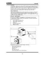
Figure D-4:
Component Layout for H 4082 BM and Later
1
(R14) Convection heater
14
(F1/2) Magnetron thermostat (275°F)
2
(M2/2) Convection fan
15
(G2) Magnetron
3
(1F1/1) Oven cavity thermostat (275°F)
16
(V1) Diode
4
(2F1/1) Thermostat -
Fan Heat
safety
cutoff (248°F)
17
(V6) Protective diode
18
(A4) High-voltage capacitor
5
(1R30) Oven temperature sensor
(PT1000)
19
(Y56) Release element
20
(3F6/6), (4F6/6) Right door lock with 2
safety switches
6
(R15) Broiler
7
(1F6/6), (2F6/6), (5F6/6) Left door lock
with 3 safety switches
21
(1A1) Control electronic (EPX)
22
(2A1) Selection electronic (EW)
8
(2T1) Lighting transformer
23
(1H3/2) Oven cavity light
9
(Z2) Interference suppression capacitor
24
(2R30) Roast probe temperature sensor
10
(M2/1) Cooling fan
Not
shown
(X5/8) Socket for roast probe
temperature sensor
11
(1N1) Power electronic (ELP) - Includes
fuse F8
12
(M21) Stirrer - wave distributor
13
(1T1) High-voltage transformer
Содержание H 4080 BM
Страница 1: ...TECHNICAL INFORMATION H 408x BM Speed Ovens 2013 Miele USA ...
Страница 15: ...Technical Information 15 H 408x BM 011 Casing Door Lock ...
Страница 25: ...Technical Information 25 H 408x BM 012 Air Duct Magnetron ...
Страница 43: ...Technical Information 43 H 408x BM 020 Door ...
Страница 47: ...Technical Information 47 H 408x BM 031 Oven Cavity Wave Distribution ...
Страница 52: ...Technical Information 52 H 408x BM 032 Convection Fan Heaters ...
Страница 58: ...Technical Information 58 H 408x BM 040 Control Panel Electrical System ...


