19
ENGLISH
x
Use only rubber-jacketed exten-
sion cables with sufficient lead
cross-section (3 x 1.5 mm
2
).
x
Do not pull on power supply
cable to unplug.
A
Danger!
x
Before starting any work, check
to see that the safety devices are
in proper working order.
x
Use personal protection gear.
x
Assume the proper operating
position:
at the front of the saw;
in front of the saw;
to the side of the line of cut.
x
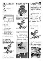
Risk of crushing! When tilting the
sawhead do not reach into the tilt-
ing range of the sawhead holder
or under the machine! Hold at the
sawhead when tilting.
x
For working, use the following:
work support – for long stock,
which would otherwise fall off
the table on completion of the
cut;
dust bag or dust collector.
x
Cut only work pieces of dimen-
sions that allow for safe and
secure holding while cutting.
x
Always hold the work piece down
on the table and do not jam it. Do
not attempt to stop the saw blade
by exerting lateral pressure. Risk
of injury if the saw blade is
blocked.
8.1
Standard Cross Cuts
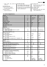
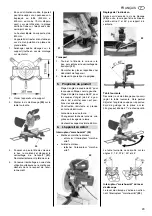
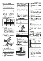
Maximum work piece dimensions (in
mm):
Starting position:
Transport locking pin pulled out.
Sawhead fully raised.
Rotating table in 0
°
position, the lock
screw of the rotating table is tight-
ened.
The sawhead is vertical (0
°)
, the tilt
lock screw is tightened.
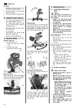
Cutting the work piece:
1.
Hold work piece against the fence.
2.
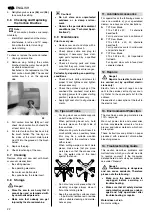
Press and hold the ON/OFF switch
(37)
.
3.
Push the safety lock
(36)
to the side.
4.
Slowly swing the sawhead fully
down, holding the handle firmly.
When sawing, exert only moderate
pressure to prevent the motor speed
to drop too much.
5.
Cut work piece in a single pass.
6.
Release the ON/OFF switch and let
the sawhead slowly return to its
upper starting position.
8.2
Mitre Cuts
3
Note:
A mitre cut cuts the work piece at
an angle against the rear guide edge.
Maximum work piece dimensions (in
mm):
Starting position:
Transport locking pin pulled out.
Sawhead fully raised.
The sawhead is vertical (0
°
), the tilt
lock screw is tightened.
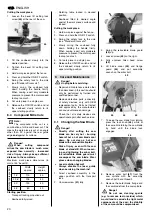
Cutting the work piece:
1.
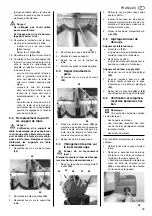
Loosen the lock screw
(39)
of the
rotating table
(38)
.
2.
Set to desired angle.
3
Note:
The rotating table engages into
positive stops at the 0°, 15°, 22.5°, 30°
and 45° position.
3.
Tighten the rotating table's lock
screw.
4.
Hold work piece against the fence.
5.
Press and hold the ON/OFF switch.
6.
Push safety lock to the side (see
"Standard Crosscuts").
7.
Slowly swing the sawhead fully
down, holding the handle firmly.
When sawing, exert only moderate
pressure to prevent the motor speed
to drop too much.
8.
Cut work piece in a single pass.
9.
Release the ON/OFF switch and let
the sawhead slowly return to its
upper starting position.
8.3
Bevel Cuts
3
Note:
A bevel cut cuts the work piece at
an angle other than 90°.
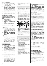
Maximum work piece dimensions (in
mm) at 45° bevel tilt:
Starting position:
Transport locking pin pulled out.
Sawhead fully raised.
Rotating table in 0
°
position, the lock
screw of the rotating table is tight-
ened.
8.
Operation
Width approx.
120
Height approx.
65
R
o
tati
ng table
p
o
sition
Width
approx.
Height
approx.
15° 110
65
22.5° 105
65
30° 100
65
45° 80
65
36
37
Width approx.
120
Height approx.
40
38
39


