


MC³ 24.96.EX O&M Manual
Page 33
08/14/01 4:34 PM/LDD
SETUP SCREEN 2
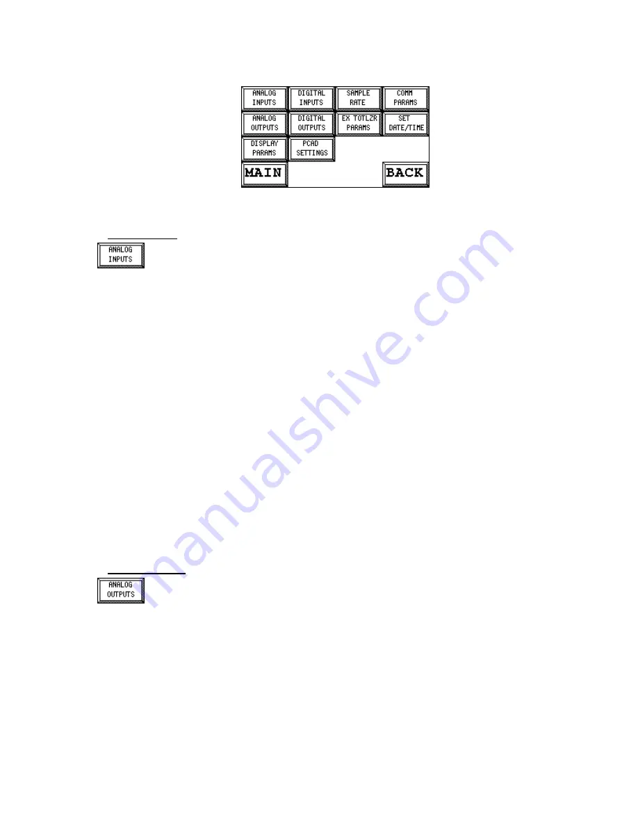
Setup Screen 2
Analog Inputs
The Analog Input #1 is used for the Feedrate setpoint, when Remote Analog Input or
Remote Analog Ratio is used. See page 17. The input signal is converted into a unipolar
20 bit number 0..1048575. A two point conversion is used to translate the raw input
counts to a usable value, expressed in engineering units for feedrate. Three parameters are
involved, as described below. The parameters are normally set using the Analog Input Setup and
Calibration procedure (page 56), but they can also be manually edited here.
A similar set of parameters are available for analog input #2. Although this input is unused in the
application, the analog input can be “borrowed” by supervisory system, such as the SuperBridge
PLC interface.
IN1 Zero Level / IN2 Zero Level
This value is the counts representing the zero value of the incoming signal. When the input signal
is set to 4 -20 mA or 2..10 V input then this value should be around 200,000 counts. If the input is
set to 0 - 20 mV then the zero level should be close to 0 counts. Limits are minimum of 0 and a
maximum of 1,040,000.
IN1 100% Level / IN2 100% Level
This value is the representation of the 100% value of the incoming signal. Normally this value will
be 1,000,000 counts representing 20 mA or 10 V (100% ) of the incoming signal. Limits are
minimum of 1 and a maximum of 1,040,000.
IN1 Scaling / IN2 Scaling
This is the value representing the full scale value used for scaling the input. Normally, this is the
Design Feedrate, but there are applications where other values can be used, especially if Remote
Ratio is used. Limits are minimum of 1 and a maximum of 100,000.
Analog Outputs
The purpose of this section is to configure the Analog Outputs. Each analog output may
be 0-20 V, 4-20 mA, 0-10 V or 2-10V. Note that the selection between voltage and
current is made with straps on the PCIO boards, while the output at zero is selected
here. The type of output may be for Feeder Control, Feedrate or Belt Load, Speed or the current
setpoint. To change the settings for any of the outputs, just press on the button to cycle through
the choices for type and output rating.


