


MC³ 24.96.EX O&M Manual
Page 26
08/14/01 4:34 PM/LDD
Gain
This is the amount of gain associated with the PID algorithm. In the MC³, gain is expressed as a
percentage. The higher the gain, the more aggressive controller behavior. A purely proportional
controller (with no integral and derivative action) would result in constant error. Too much gain can
cause the controller to go unstable.
Integral
Integral action adjusts the belt speed using the accumulated (integral of) the error. The integral
term is expressed in units of 1/sec. Since a purely proportional controller will result in a constant
error, the integral term eliminates this error. As with gain, too much integral action can result in an
unstable controller.
Derivative
Derivative action adds dampening to the controller. The derivative term is expressed in units of
seconds. The derivative term acts against changes in the error. This has the effect of minimizing
overshooting the setpoint.
SCR Accel %/s and SCR Decel %/s
There are also two other parameters that provide Output Dynamic Protection. The two parameters
are available to limit the acceleration and deceleration of the controlled device. Their purpose is to
eliminate damage to the motor drive circuit, motor, drive mechanism and belt. For some materials,
it is also necessary to limit acceleration and deceleration of the belt to prevent material from
bouncing around on the belt or falling off the belt. The parameters are expressed as percent per
second.
Start Speed
This is a feature that, when enabled, makes the belt sped quickly jump to a pre-calculated speed at
feeder start-up. This is useful in blending applications or when a quick start is required. The
controller calculates the required belt speed for the current setpoint based on the current belt load,
and generates an output signal for the belt drive that will produce this speed, based on the
controller’s experience. Enter a value of 1 to enable this feature.
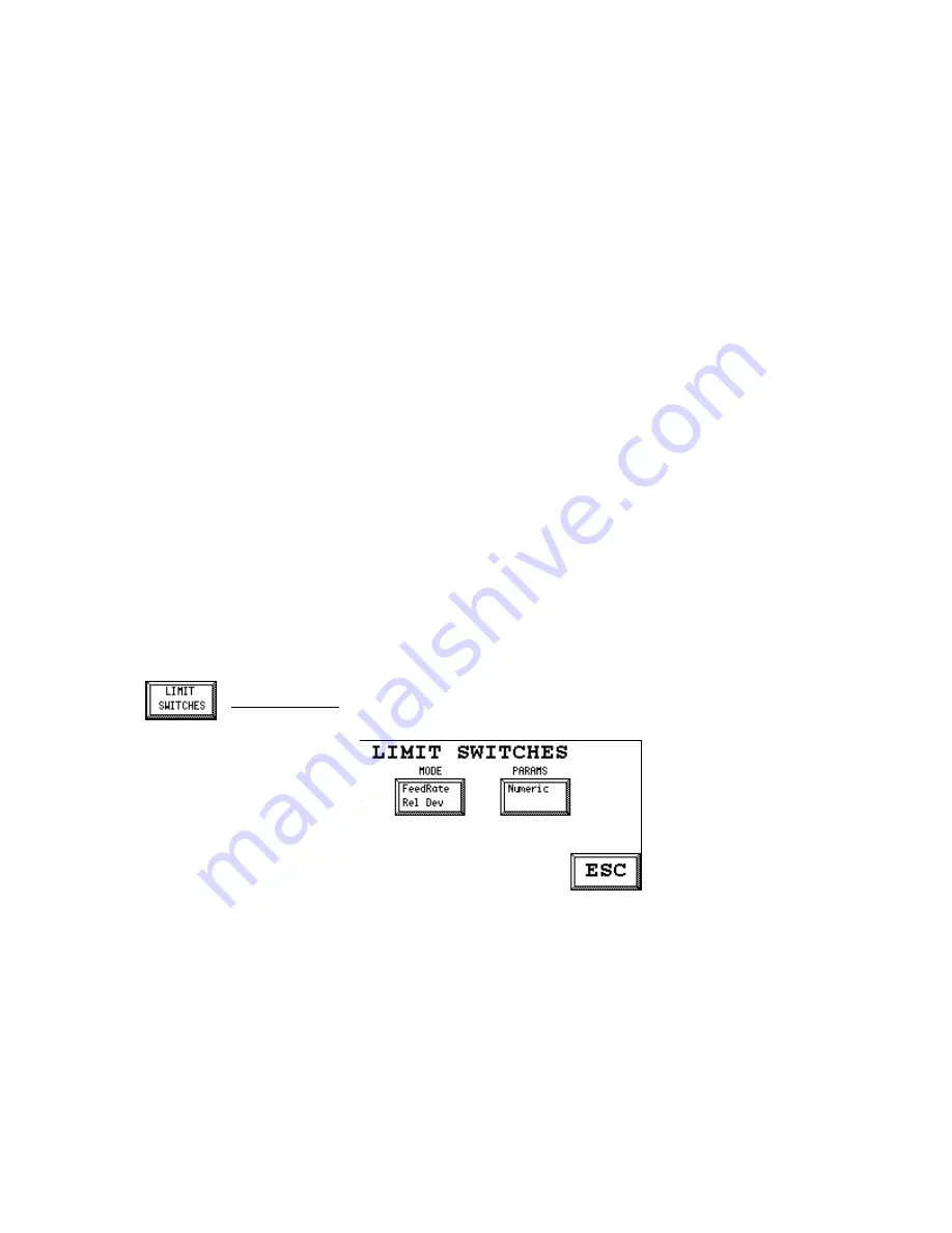
Limit Switches
Three feedrate alarm indicators located on the Main Screen, and nine feedrate alarm Logical
Outputs are affected by the controller operating mode selected. The operating modes may be
changed during the normal operation of the feeder as required. (See Controller modes page 14.)
The Logical Outputs can be mapped to physical outputs for external indication and alarming. (See
Digital I/O Mapping on page 34.) The nine feedrate Logical Outputs will only be active when all the
following conditions have been met:
1. Feedrate Mode is selected.
2. Not in Manual Speed setpoint.
3. The logical inputs Run Permission and Gravimetric are on.


