


MC³ 24.96.EX O&M Manual
Page 17
08/14/01 4:34 PM/LDD
current depending on jumper setting on the PCIO board (see Analog Outputs on page 70 for more
information).
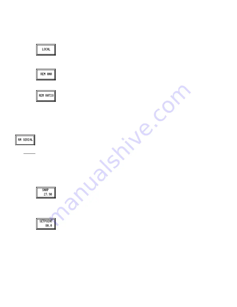
Local
When this mode is selected, a Feedrate setpoint can be entered by the operator. This
setpoint is in engineering units for rate. This mode allows the operator entered setpoint
to be used by the controller in conjunction with the current feedrate to develop closed-
loop control of the feeder.
Remote Analog Input
This Setpoint mode allows the setpoint value to be input through the Analog Input in
relation to the IN1 Scaling parameter, see IN1 Scaling / IN2 Scaling (page 33). Default
IN1 Scaling is the Design Feedrate Capacity. See Design Capacities (page 25).
Remote Analog Ratio
This mode scales the External Feedrate setpoint as a percentage of the incoming
analog input signal. Scaling is the same as Remote Analog. This allows multiple feeders
to be connected to a single signal with each feeder assigned a particular percentage of
the signal as a setpoint.
For example, three feeders are to be used set up to provide material to a process using one analog
input for control. Feeder number one provides 25%, feeder number 2 provides 35% and feeder
number 3 provides 40% of the material needed for the total process. When the setpoint changes
for the process all three feeders will properly scale the outputs for the new setpoint.
Remote Serial
This setpoint mode allows the MC³ Controller to receive a setpoint from a remote device through
the serial port such as a computer or a PLC/SuperBridge Controller. This method requires that the
remote device is connected to the controller via the RS-485 serial port.
NOTE:
When the controller is to be used in SuperBridge or any other system which transmits setpoint
information using Serial Communications, the Remote Serial mode must be selected. The rules and
format of the data exchange is described in [1].
When the logical input Serial Setpoint is enabled and there is no communications time-out, the
setpoint screen will display a Fall back Setpoint menu allowing you to enter a method and value for
the controller to default to when serial communications are interrupted.
Snap Button
The Snap button is used only in the Manual Speed and Local setpoint methods. This
function is used to ‘capture’ the current feedrate to the setpoint. The current feedrate is
displayed in this button.
If this button is not available for a method, the current feedrate will be displayed.
Setpoint Button
This button allows numeric editing of the setpoint. This button is only available for the
Manual Speed, Local, and Remote Analog Ratio methods.
If this button is not displayed, the current setpoint for the method selected is displayed


