


C
ONNECT
STC
S
TO
A
MPS
/M
OTOR
/E
NCODER
4-22
P
C
I
C
o
n
n
ec
ti
o
n
s
fo
r
E
n
co
d
er
S
ig
n
a
ls
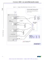
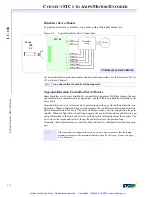
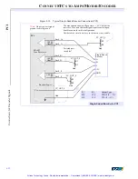
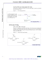
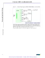
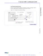
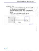
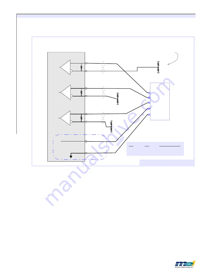
Figure 4-19
Typical Single-Ended Encoder Connections (PCI)
PCI
100
Ohm
Enc0_A-
Single-Ended
Encoder
I
B
A
+5V
GND
100
Ohm
Enc0_B-
100
Enc0_I-
Vcc
Gnd
5V_OUT_0
EIA 422
Line Receivers
Encoder Power
Single-Ended Encoder to PCI
Twisted pair
in cables*
R1
R2
Output Type
820
820
CMOS (0 - +5V)
620
330
TTL (0 - +3V)
The bias circuits shown will ge/- .5V Vdiff at the
receivers. Also note that each signal requires an indepen-
dent bias network in this configuration.
Put these bias circuits as close to the encoder as possible.
*Note:
Do not connect signal
ground to shield ground.
R1
R2
Gnd
5V_OUT_0
R1
R2
Gnd
5V_OUT_0
R1
R2
Gnd
5V_OUT_0
Artisan Technology Group - Quality Instrumentation ... Guaranteed | (888) 88-SOURCE | www.artisantg.com


