T
EST
S
YSTEM
6-2
C
lo
se
d
-L
o
o
p
S
y
st
em
s
S
te
p
1
:
C
o
n
n
ec
t
E
n
co
d
er
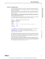
Step 1: Connect Encoder
Turn off the computer.
Attach all encoder leads according to the manufacturer’s wiring dia-
gram and the instructions provided in this manual.
Turn on the computer.
Note that the controller provides the +5V power (which comes direct-
ly from the host computer’s power supply) to the encoder for most brush servo and step motor
systems.
If the servo motor uses the encoder for commutation and the servo amplifier provides the en-
coder power, the servo amp
must be turned on
to test the encoders.
Step 2: Test Encoder Connections
Start the Motion Console program. Choose an axis in the Hardware Summary window and
click the
Configure Axis
button. In the
Axis Configuration
property page verify that the axis’
configuration is accurate for your system. Close the property page and open the
Axis Operation
window which will display the actual encoder position.
Turn the motor shaft/encoder by hand. The counts in the
Actual
field should increase and de-
crease normally. Check to see that 1 revolution of the encoder provides the correct number of
encoder counts (number of encoder lines x 4).
Step 3: Connect the Motor
Turn off the power to the computer.
Connect the analog motor command or step/direction lines.
Turn the computer power on.
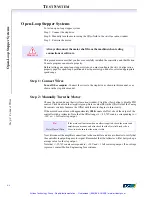
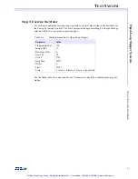
Step 4: Manually Turn the Motor
Click the
Abort
button in the
Axis Operation
window to disable PID control. Turn on power
for the servo amp/step drive. The shaft of the servo motor should now turn freely (for torque
mode amplifiers).
Enter a value (
10
) in the
Offset
field of the
Tuning Parameters
display (still in the
Axis Oper-
ation
window) to start turning the motor. Increase the
Offset
value past 10 until the motor be-
gins to turn slowly.
If the motor does not turn with approximately
1000
counts of offset, check the output of the
controller with a voltmeter. Note that the
Offset
field range is +/-32,767 counts, corresponding
to +/-10V or +/- full scale step output.
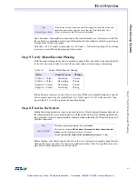
Tip!
Encoder Counts
Bounce
If the encoder counts “bounce” by one count when the motor shaft is turned
(i.e. change up and down one count when the encoder is tuned), the likely
problem is that the one side of the encoder (A or B) is not connected.
Check the connections carefully.
W
ARNING
!
Do not attach the motor signal wires yet!
W
ARNING
!
Be sure the power to the servo amp/step drive is off!
Artisan Technology Group - Quality Instrumentation ... Guaranteed | (888) 88-SOURCE | www.artisantg.com

