S
ETUP
.E
XE
C-11
C
o
n
fig
u
re
M
en
u
A
xi
s C
o
n
fig
u
ra
tio
n
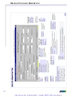
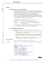
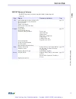
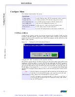
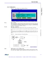
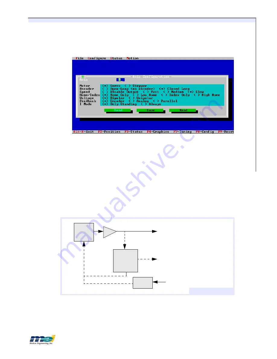
Axis Configuration
Figure C-5
The Configure/Axis Configuration Window
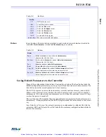
Motor
Servo
or
Stepper
This selection is used to enable/disable the step pulse output for a given pair of axes. Selecting
“step” will enable the step output for the pair of axes (0 and 1, 2 and 3, etc.). The analog output
is available regardless of the selection. When the motor type is changed, a set of default tuning
parameters will be loaded into SETUP for that axis.
Encoder
Open-loop
or
Closed-loop
This selection enables you to indicate if a pair of axes is to be open-loop or closed-loop.
If closed-loop is selected, the controller will use feedback from an external device to close the
loop.
If open-loop are selected (and
Step
was selected on
Motor
line), the board will direct the step
output back into the encoder input for the axis, in effect digitally closing the loop on the con-
troller
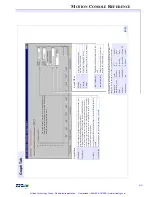
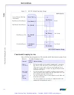
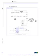
Figure C-6
Internal Architecture to Control Step Motors
Speed
Disable Output
or
Fast
or
Medium or Slow
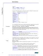
This selection sets the maximum pulse rate for the step output in either open-loop or closed-
loop mode. Whenever
Step
is selected (on
Motor
line), the step speed range must be set. The
PID
Filter
D/A
Voltage
to
Frequency
Converter
Analog Output
Active if Stepper Axis
Step
Output
Encoder
Inputs
Active if Open-Loop Axis
Active if Closed-Loop Axis
Internal Architecture
Artisan Technology Group - Quality Instrumentation ... Guaranteed | (888) 88-SOURCE | www.artisantg.com

