47
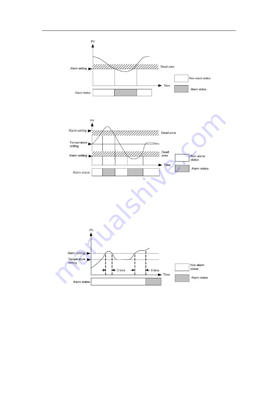
Figure 5-18 Schematic diagram of
low limit
and
deviation low
Figure 5-19 Schematic diagram of
deviation high/low
5.3.3 Alarm delay
When the deviation between the measured value PV and the set value SV reaches the alarm
setting value, the alarm delay function will remain in the non-alarm state. No warning will be
given until the number of input samples exceeds the number of alarm delay.
For example, when the number of alarm delay is set to 5, it is shown in figure 5-20:
Figure 4-20 Alarm delay time
5.4 Multi-step function
MTC can perform multi-step function. When the temperature of each section of the channel is set to a
given value, the execution time of each section, the repeating start segment, the repeating end segment,
and the repeating number of times, the corresponding bit of the multi-step set execution mark (BFM#552)
is written as 1, then MTC starts to perform multi-step set value execution, starting from the first segment,
until the end of the eighth segment. The set value will be maintained at the set value of paragraph 8 after


