20
the controller, which may cause fire, failure and wrong operation.
3.Remove the foreign body immediately after installation and wiring. Please cover the terminal cover of
the product before electrifying to avoid electric shock.
4.At the end of the installation of the newly purchased MTC, it is necessary to ensure that there is no
foreign body on the ventilation surface, including dust-proof paper and other packaging items, otherwise
it may lead to poor heat dissipation during operation, causing fire, failure and wrong operation.
5.Avoid wiring and unplugging cables in live state, or electric shock or circuit damage will be easily
caused.
6.Installation and wiring must be firm and reliable. Poor contact may lead to incorrect operation.
7.The input or output cables of high frequency signals and the cables transmitting analog signals should
be twiped shielded cables to improve the anti-disturbance performance of the system.
8.Please access 24Vdc power supply according to the instructions in this manual. Connecting ac power
to the terminal will burn MTC.
9.The input and output signal lines connected to MTC shall not be arranged side by side with other
high-power or high-interference lines to reduce interference.
2.2.2 Wiring instructions
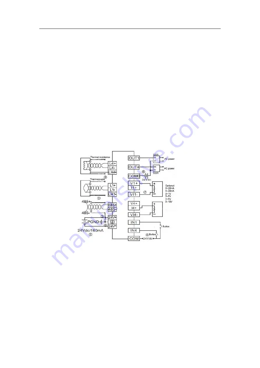
User terminal input wiring is shown in Figure 2-4.
Table 2-1 MTC-04-NVT enter the user terminal wiring diagram
Figure
①
~
⑦
wiring must be noted that seven aspects:
①
The rmocouple (thermal resistance) signals suggested accessing by shieded compensation cable. Cables away
from power lines or other wires may produce electromagnetic interference. It is recommended to use less than
100 m compensation cable (connecting cable) that be suscepted by noise interference Compensation cable (cable)
exist resistance, will introduce measurement error, adjustment feature to resolve this issue, please refer to the specific
operation "MTC-04-NVT thermostat user manual."
②
Thermal resistance (type Pt100, JPt100, Cu100, Cu50) required the three-wire connection.
③
If there is too much electrical interference, the shield wire
(thermocouple compensationcable shielding terminal, thermal resistance of the connecting cable shielding terminal
485 linescreen) should be connected to ground terminal PG.
④
The thermostat grounding PG should be good grounding.
⑤
24V power supply can use the main output of 24Vdc auxiliary power supply module, you can also use the other to


