16
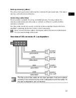
Arrangement of the ISO socket blocks on the car radio
ISO Block
BLOCK B – Speakers
BLOCK A – Electricity supply
1
Rear right +
1
2
Rear right -
2
3
Front right +
3
4
Front right -
4
Permanent plus (permanent
12V voltage);
Terminal 30
5
Front left +
5
Car antenna (also for
external amplifiers, etc.)
6
Front left -
6
7
Rear left+
7
Switched plus (switched 12
V voltage through the
ignition lock); Terminal 15
8
Rear left -
8
Mass; Terminal 31
Problems due to incorrect cable connections
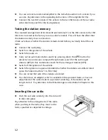
The standard arrangement of the permanent plus and the switched plus cable is
reversed in the ISO connector for ISO block A at the factory in some vehicle models. If
this is the case, some functions will be impaired, e.g. the station memory will be lost.
The cable for switched plus (red) and the cable for permanent plus (yellow) will have
to be exchanged in the ISO socket block to remedy this. Suitable adapters are available
for this in the specialist trade.


