


User Manual
B
WARNING
•
Keep the robot un-powered while installing/removing a tool to its ange.
•
Do not overpass the robot payload (0.5 kg).
•
Securely fasten the tool to the robot ange.
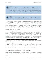
Note that since joint 6 is multi-turn, there is no way of knowing the angle of joint 6 (even
approximately), unless the robot is activated and homed. Therefore, prior to mounting an
end-eector, it is important that you activate and home your robot, rotate joint 6 to its zero
position, and nally unpower the robot. However, if the screw on the ange of the robot
is not as in Fig. 19b when
θ
6
= 0
◦
, then you need to follow the procedure described in the
subsection Homing of the
(a) Closeup
Ø
20
units: mm
Ø
9 H6,
É
2.2
M3X0.5,
É
4
BCD 15.5
4X equally spaced
Ø
3,
É
3.5
BCD 15.5
2X equally spaced
(b) Dimensions
Figure 19: The mechanical interface (ange) of the Meca500. The ange is the
20
disk,
inside the black isolation ring, and is the only one to rotate when joint 6 rotates.
B
CAUTION
•
Make sure that joint 6 is approximately at
0
◦
before attaching an end-eector.
•
Do not over-tighten the M3 screws.
•
Attach the tool cabling in such a manner that it obstructs as little as possible
the motions of the robot.
•
Unless you plug the connector of our own gripper, keep the cover (screw cap,
not shown in Fig. 19a) of the tool I/O port in place at all times.
Page 34 of 38
Copyright c
2020 by Mecademic Inc.


