


User Manual
TCP/IP or EtherCAT, activate the robot, and nally home it. Of course, you will also need
to manage the stream of commands being sent to the robot. For example, if a PLC sends
commands to the robot, while the robot is powered o, the program that runs on your PLC
will need to be able to detect and manage this situation. To do so, you can get a signal from
the intelligent power supply that power to the robot has been cut by connecting your PLC
to the D-SUB connected, as will be explained in the following pages.
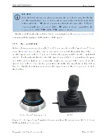
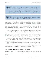
9.1 LEDs
The power supply is equipped with three LEDs. As long as the power supply is switched
on (using the on/o button shown in Fig. 16b) and connected to an AC source that sup-
plies voltage at 90264 V at frequency of 5060 Hz, the green LED next to Power stays
illuminated. Supplying AC voltage outside this range may damage the power supply.
Once the power supply is switched on, the yellow Status LED indicates the status of the
power supply. If the yellow LED is o, you need to press the RESET button, which sends
power to the robot. If the proper Meca500 is correctly connected to the power supply, the
yellow LED will turn on and stay lit.
If, in any situation, the yellow LED blinks regularly, this means that an emergency stop
(either the one on the power supply or the external one) or the external protective stop 2
is activated. You need to release the emergency stop or remove the cause for the protective
stop 2 and then press the RESET button.
(a) front view
(b) back view
Figure 16: The intelligent power supply
Copyright c
2020 by Mecademic Inc.
Page 29 of 38


