


User Manual
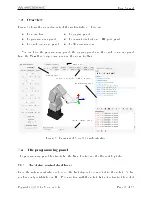
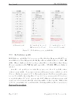
Figure 14: Robot posture when its TRF is at
x
= 250
mm,
y
= 0
mm,
z
= 150
mm,
α
= 0
◦
,
β
= 90
◦
,
γ
= 0
◦
with respect to its WRF
NOTICE
The Cartesian coordinates displayed above the robot in the web interface are
those of the Tool Reference Frame (TRF) with respect to the World Reference
Frame (WRF). Both frames are displayed in the web interface. By default, the
TRF is located at the ange of the robot and the WRF at the bottom of the
robot's base. The origin of the TRF is called the TCP (Tool Center Point).
NOTICE
We use Euler angles (
α
,
β
,
γ
) to dene the orientation of a second reference
frame with respect to a rst one. More specically, if we consider both frames
initially coincident, we rotate the second frame about its
x
axis at
α
degrees,
then about its
y
axis at
β
degrees, and nally about its
z
axis at
γ
degrees.
You can move the robot to the new end-eector pose following these steps:
•
Clear the programming text eld, type MovePose(250,0,150,0,90,0), and press
Ù
.
OR
•
In the quick command panel, select MovePose, ll in the arguments with the values
250, 0, 150 , 0, 90, and 0, and click on
○
.
Figure 14 shows the resulting robot posture.
You can now jog the robot in both joint and Cartesian space. Note that when a joint
reaches its limit while jogging, the robot stops but no message is displayed in the response
log. Furthermore, if you jog the robot in Cartesian space, you can also run into singularities
Copyright c
2020 by Mecademic Inc.
Page 23 of 38


