IOMM AGR-1
AGR 070A through 100A
57
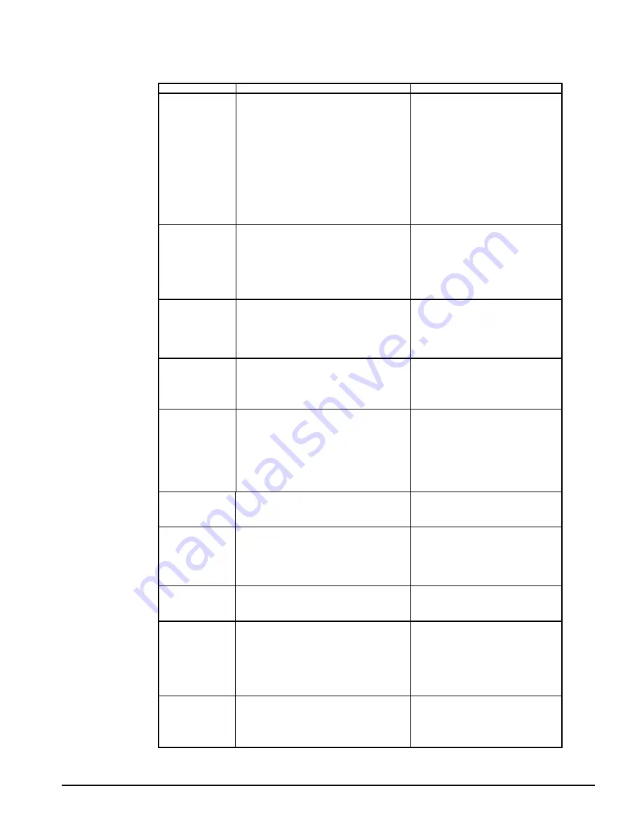
UNT Controller Troubleshooting Chart
PROBLEM
POSSIBLE CAUSES
CORRECTIVE ACTIONS
Compressor
Will Not Run
1.
Main switch, circuit breakers open.
2. Fuse
blown.
3.
Thermal overloads tripped or fuses blown.
4.
Defective contactor or coil.
5.
System shut down by safety devices.
6.
No cooling required.
7.
Liquid line solenoid will not open.
8.
Motor electrical trouble.
9. Loose
wiring.
1. Close
switch.
2.
Check electrical circuits and motor
winding for shorts or grounds. Possible
overloading. Replace fuse or reset
breakers after fault is corrected.
3.
Overloads are auto reset. Check unit
closely when operating again.
4.
Repair or replace.
5.
Determine type and cause of shutdown
and correct it before resetting safety.
6.
None. Wait for load.
7.
Repair or replace.
8.
Check motor for opens, shorts circuit or
burnout.
9.
Check all wire junctions. Tighten all
terminals.
High Discharge
Pressure
1. Dirty
condenser
coils.
2.
Fan not operating.
3.
High Ambient conditions.
4.
High return water temperature.
5.
Overcharge of refrigerant.
6. Non
condensable.
7.
Discharge valve partially closed.
1. Clean.
2.
Check fan motor, contactor, contactor
coil, fan pressure switch. Repair or
replace defective part.
3.
Check against design conditions.
4.
Disable a compressor on each.
5.
Remove excessive amount of charge.
6.
Remove non condensable.
7.
Back seat valve.
Low Discharge
Pressure
1.
Fan contactor failed in closed position.
2.
Fan pressure switch defective.
3.
Low ambient temps.
4.
Low on refrigerant charge.
5.
Reduced chilled water flow.
6.
No load and on hot gas bypass.
1.
Repair or replace.
2.
Replace pressure switch.
3.
Install SpeedTrol Kit.
4. Add
refrigerant.
5.
Check flow and correct.
6.
Adjust hot gas bypass to maintain a
higher evaporator pressure.
High Suction
Pressure
1.
Excessive load (high return water temp).
2.
Controller not staging up.
3.
Compressor capacity reduced.
4.
Can be associated with high condenser
pressure.
1.
Check water flow, reduce load.
2.
Check UNT controller. Replace if
defective.
3. Replace
compressor.
4.
Check reasons for high condenser
pressure.
Low Suction
Pressure
1.
Low refrigerant charge.
2. Defective
expansion
valve.
3. Dirty
filter
drier.
4. Reduced
water
flow.
5.
Hot gas bypass valve not set properly.
6.
Liquid line solenoid valve not opening.
7.
UNT controller defective.
8.
Gasket failure in evap head ring.
1. Add
refrigerant.
2.
Check operation. Repair or replace.
3. Replace
cores.
4.
Increase water to design GPM.
5.
Set valve for a higher pressure.
6.
Repair or replace.
7.
Check water sensor, set point dial,
control band dial. Calibrate, repair or
replace.
8. Replace
gasket.
Compressor Oil Loss
1.
Excessive refrigerant flood back.
2. Defective
crankcase
heater.
3. Low
refrigerant
change.
4.
Hot gas bypass not set properly.
1.
Check TXV. Repair or replace.
2. Replace
heater.
3. Add
refrigerant.
4.
Increase hot gas flow.
Compressor
Overloads or Circuit
Breakers Open
1. Low
line
voltage.
2.
High compressor amps.
3.
Loose power wiring.
4.
High condenser pressures.
5. Single
phasing.
1.
Check incoming voltage. Report to
electrical supplier.
2.
Determine cause and correct.
3.
Tighten all connections.
4.
Refer to High Condenser Pressure.
5.
Replace fuses or breaker.
Compressor Internal
Motor Switch Open
1. Compressor
amps
high.
2. Motor
winding
damaged.
1.
Refer to the above concerning high
compressor amps.
2.
Check motor winding resistance.
Replace if defective.
Freeze Protection
Trips
1.
Pressure transducers defective.
2.
Low water flow.
3.
Low loads / erratic water flow.
4.
Controller stage timing.
5. Defective
TXV.
6.
Hot gas bypass not set properly.
7.
Low ambient operation.
1.
Compare output to actual refrigerant
pressures.
2.
Check water GPM and correct.
3.
Check pump operation, water strainer, air
handler control valves.
4.
Check timing and reset as necessary.
5.
Check and repair or replace.
6.
Set hot gas bypass.
7.
Install SpeedTrol, wind baffles.
Erratic Loading and
Unloading
1.
Chilled water flow erratic.
2. System
load
erratic.
3.
Bad water sensor.
4. Reset
function
calibration.
5.
Defective UNT controller.
1.
Check for reasons and correct.
2.
Check water flow control valve operation.
3. Replace.
4. Re-calibrate
5. Replace
Содержание AGR 070AS
Страница 20: ...20 AGR 070A through 100A IOMM AGR 1 Figure 9 Typical Field Wiring with Global UNT Controller...
Страница 21: ...IOMM AGR 1 AGR 070A through 100A 21 Figure 10 Typical Field Wiring Diagram with MicroTech Controller...
Страница 22: ...22 AGR 070A through 100A IOMM AGR 1 Figure 11 Standard Single Point Connection with FanTrol...
Страница 23: ...IOMM AGR 1 AGR 070A through 100A 23 Figure 12 Standard Single Point Connection with Optional SpeedTrol...
Страница 24: ...24 AGR 070A through 100A IOMM AGR 1 Figure 13 Unit Control Schematic 2 compressor UNT...
Страница 25: ...IOMM AGR 1 AGR 070A through 100A 25 Figure 14 Staging Schematic 2 compressor 4 stage UNT...
Страница 26: ...26 AGR 070A through 100A IOMM AGR 1 Figure 15 Staging Schematic 2 compressor 6 stage UNT...
Страница 27: ...IOMM AGR 1 AGR 070A through 100A 27 Figure 16 MicroTech Controller Schematic...
Страница 28: ...28 AGR 070A through 100A IOMM AGR 1 Figure 17 Unit Control Schematic MicroTech...
Страница 29: ...IOMM AGR 1 AGR 070A through 100A 29 Figure 18 Staging Schematic 4 stage MicroTech...
Страница 30: ...30 AGR 070A through 100A IOMM AGR 1 Figure 19 Staging Schematic 6 stage MicroTech...
Страница 31: ...IOMM AGR 1 AGR 070A through 100A 31 Figure 20 Unit Control Schematic 2 compressor MicroTech...
Страница 32: ...32 AGR 070A through 100A IOMM AGR 1 Figure 21 UNT Instrument Layout See legend on page 34...
Страница 33: ...IOMM AGR 1 AGR 070A through 100A 33 Figure 22 MicroTech Instrument Layout See legend on page 34...
Страница 35: ...IOMM AGR 1 AGR 070A through 100A 35 Figure 25 MicroTech Sensor Layout...
Страница 99: ...IOMM AGR 1 AGR 070A through 100A 99 Notes...
Страница 100: ...Post Office Box 2510 Staunton Virginia 24402 USA 800 432 1342 www mcquay com...


