McQuay ACZ 045A Скачать руководство пользователя страница 56

56

IOMM ACZ/AGZ-1

DISPLAYS, SYMBOLS, KEYS, AND BUTTONS

The Zone Terminal simultaneously displays three set points or sensed values.  In addition, flashing
symbols indicate when items are in a state of alarm.  The keys, buttons, displays, and symbols are
explained below.

Table 20, Displays, Symbols, Keys, Buttons

DISPLAYS, SYMBOLS,

KEYS, BUTTONS

DESCRIPTION

Display Button

 1, 2, 3

Select the value you want to monitor or

adjust.

Enter Key

Use to commit your changes.

Adjustments are not processed unless

you press Enter.

Flashing Numbers

Appear in Display 1, 2, or 3 to indicate

numbers you can adjust.  Numbers that
do not flash are monitor only numbers.

Flashing

s

s

m

m

, ( | )

Shows an item is in alarm.

Mode Selector Button

Press this button to select Operating

Modes:  Monitor, Adjust, Password, Time

Scheduling.  A green Mode Indicator light

moves through the modes.

On/Off Status Symbols( | )

for On/a circle (

m

m

) for Off

Observe On/Off conditions of a point in

the HVAC controller with these symbols.

A bar (| ) for On, a circle (

m

m

) for Off.

These are always monitor only items.  If

the symbol flashes, item is in alarm.

Red Alarm Light

Flashes anytime a problem exists

regardless of which Operating Mode you

have entered.

Up (

) or Down (

) Arrow

Keys

Use these keys to adjust a flashing

number.

l

l

Appears in the displays, and corresponds

to the item you are monitoring or

adjusting.

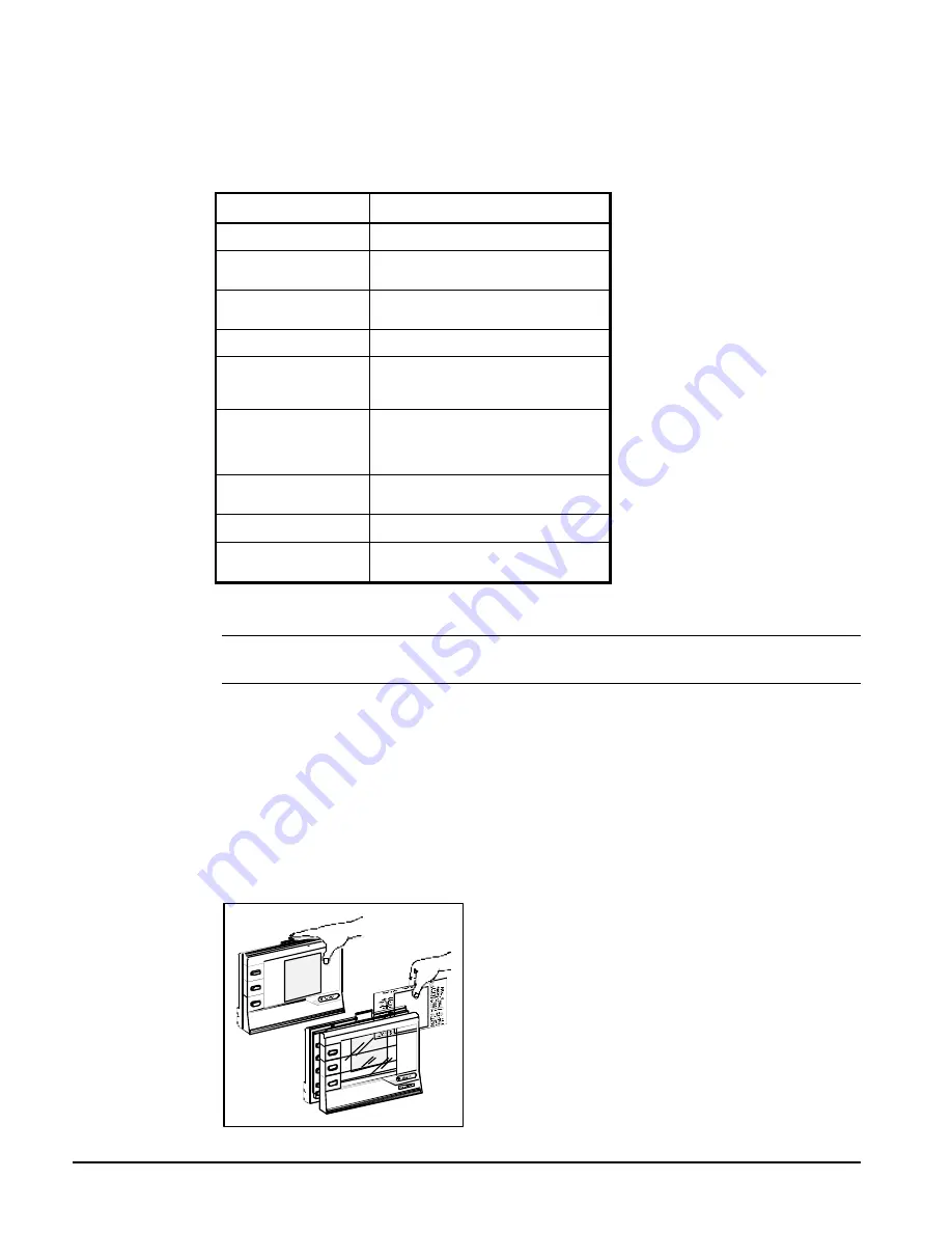
INSTALLING THE PLASTIC LABELS

Note:

 The insert is normally factory-installed.  These steps are required only if the insert is not

already installed.

To use the ZT, you'll need the plastic label which is included with your ZT.

Insert

The clear plastic Insert is a custom-made label unique to your chiller.  Use this Insert when monitoring
or adjusting specific items of your system:

1.


With the ZT on a flat surface, press the white tab with your index finger (Figure 27).

2.


Pull the front cover of the ZT away from the back and slide the Insert into position.

3.


Press the ZT together.  With the Insert in place and the ZT connected, the 

l

 in the top position of

each display lines up with the first word.

Figure 27, Installing the Insert

Содержание ACZ 045A

Страница 1: ...ler Part Number 074644101 Effective February 2000 Supersedes IOMM ACZ AGZ 1997 McQuay International AIR COOLED SCROLL COMPRESSOR SPLIT SYSTEMS Chiller w Remote Evaporator AGZ 035AM 050AM Condensing Un...

Страница 2: ...Cooler 45 Global UNT Controller AGZ AM 46 General Description 46 Optional Sensors 46 Controller Inputs Outputs 48 Additional UNT Features 51 Alarms 53 ZONE TERMINAL optional 54 Zone Terminal Glossary...

Страница 3: ...ler or DX coil No capacity control is supplied nor are any liquid line specialties nor evaporator Model CDE This is a DX water chiller that can be used in conjunction with the Model ACZ condensing uni...

Страница 4: ...ing vehicle away from the unit to prevent damage to the sheet metal cabinet and end frame see Figure 1 To lift the unit 2 1 2 64mm diameter lifting holes are provided in the base of the unit Arrange s...

Страница 5: ...l and for servicing Provide service access to the evaporator compressors electrical control panel and piping components as shown in Figure 3 Do not allow debris to accumulate near the unit Air movemen...

Страница 6: ...6 IOMM ACZ AGZ 1 Figure 3 Clearance Requirements...

Страница 7: ...tal Unit Size Size lb kg lb kg lb kg lb kg lb kg 030A 838 380 944 428 773 351 870 395 3425 1554 035A 030AM 838 380 944 428 773 351 870 395 3425 1554 040A 035AM 850 386 960 435 785 356 885 401 3480 157...

Страница 8: ...to a separate 110V supply circuit should the evaporator be located in an area subject to freezing temperatures If used all water piping to the unit must also be protected to prevent freezing 9 If the...

Страница 9: ...he unit control center at terminals 5 and 6 There is also a set of normally closed contacts on the switch that can be used for an indicator light or an alarm to indicate when a no flow condition exist...

Страница 10: ...wer Multiply the water system power by Power correction factor from Table 4 or Table 5 Test coolant with a clean accurate glycol solution hydrometer similar to that found in service stations to determ...

Страница 11: ...65 0 995 0 909 0 947 12 6 7 0 992 1 011 0 970 0 998 0 914 0 949 14 6 8 0 997 1 014 0 973 1 001 0 919 0 952 2000 ft 610 m 16 8 9 1 000 1 016 0 975 1 002 0 921 0 953 6 3 3 0 966 1 016 0 944 0 999 0 894...

Страница 12: ...0AM 13 4 117 7 38 33 6 195 12 30 5 7 73 4 61 Minimum and maximum flows are established to ensure the Delta T for each unit size falls within the 6 16 F range for proper unit control Evaporator Flow an...

Страница 13: ...e piping system A similar problem to a lesser extent occurs when the equipment is oversized for the available cooling load In short extreme care should be exercised to assure that both piping and cont...

Страница 14: ...trainment of the lubricating oil up any vertical risers at the minimum tons for the circuit See d above and ASHRAE Table 2 13 If the line size selected will not maintain satisfactory oil return in a s...

Страница 15: ...ed below ground a suitable sized suction accumulator must be installed ahead of the compressor to interrupt liquid refrigerant slugs at start up Long Vertical Riser Installation Where job conditions r...

Страница 16: ...can be sized for a pressure differential from 80 to 180 psi but not more than 180 psi and should be auto resetting as the pressure is relieved CAUTION The liquid line should not include a check valve...

Страница 17: ...must be sized for a maximum velocity of 100 fpm Piping sizes for this are shown in the ASHRAE tables Note If the interconnecting piping described above contains a Seasontrol type head pressure control...

Страница 18: ...ned Height x Finned Length In 80 x 83 5 80 x 83 5 80 x 83 5 80 x 83 5 80 x 83 5 80 x 83 5 80 x 83 5 80 x 83 5 Finned Height x Finned Length mm 2032 x 2121 2032 x 2121 2032 x 2121 2032 x 2121 2032 x 21...

Страница 19: ...75 100 Standard Staging Circuit 2 in Lead Standard 4 Stages 0 25 50 75 100 0 27 50 77 100 0 25 50 75 100 CONDENSERS HIGH EFFICIENCY FIN AND TUBE TYPE WITH INTEGRAL SUBCOOLING Coil Face Area Sq Ft 46...

Страница 20: ...00 Standard Staging Circuit 2 in Lead Standard 4 Stages 0 25 50 75 100 0 28 50 78 100 0 25 50 75 100 CONDENSERS HIGH EFFICIENCY FIN AND TUBE TYPE WITH INTEGRAL SUBCOOLING Coil Face Area Sq Ft 46 4 46...

Страница 21: ...bject to below freezing temperatures The heater comes with a receptacle plug which can be used as is or removed to hard wire to a power supply Control Wiring AGZ AM chillers are equipped with either a...

Страница 22: ...25 100 All Electrical Data notes are on page 23 Table 12 AGZ AM ACZ A 60 Hz Compressor Condenser Fan Motor Amp Draw Rated Load Amps Locked Rotor Amps Compressors Compressors Across The Line ACZ Unit S...

Страница 23: ...r RLA plus 100 of RLA of all other loads in the circuit including the control transformer 2 If the control transformer option is furnished no separate 115V power is required 3 If a separate 115V power...

Страница 24: ...for reduced inrush start are for the first winding only If the unit is equipped with SpeedTrol motors the first motor is a single phase 1 hp motor with a LRA of 7 3 amps at 460 volts 14 5 amps at 208...

Страница 25: ...PARATE EVAPORATOR HEATER POWER OPTION IS USED REMOVE WIRES 540 AND 545 120VAC CONTROLPOWER 120VAC TB3 19 28 FACTORY SUPPLIED ALARM FIELD WIRED ALARM BELL ALARM BELL OPTION 24VAC GND TB7 140 141 AUTO O...

Страница 26: ...D 545 9 10 5A 24V OR 120VAC 120VAC CONTROL POWER 120VAC BY OTHERS N CHW PUMP RELAY BY OTHERS SOLID STATE RELAY 24V OR 120VAC 1 5 AMPS MAX TB3 19 28 FACTORY SUPPLIED ALARM FIELD WIRED ALARM BELL ALARM...

Страница 27: ...IOMM ACZ AGZ 1 27 Figure 12 AGZ AM Single point Connection with FanTrol...

Страница 28: ...28 IOMM ACZ AGZ 1 Figure 13 AGZ AM Single point Connection with SpeedTrol...

Страница 29: ...IOMM ACZ AGZ 1 29 Figure 14 AGZ AM Unit Control Schematic UNT...

Страница 30: ...30 IOMM ACZ AGZ 1 Figure 15 AGZ AM Staging Schematic UNT...

Страница 31: ...IOMM ACZ AGZ 1 31 Figure 16 AGZ AM MicroTech Controller Schematic...

Страница 32: ...32 IOMM ACZ AGZ 1 Figure 17 AGZ AM Unit Control Schematic MicroTech...

Страница 33: ...IOMM ACZ AGZ 1 33 Figure 18 AGZ AM Staging Schematic MicroTech...

Страница 34: ...34 IOMM ACZ AGZ 1 Figure 19 ACZ Field Connection Diagram No Capacity Control...

Страница 35: ...IOMM ACZ AGZ 1 35 Figure 20 ACZ Field Wiring Diagram Capacity Control Staging...

Страница 36: ...X Y Z OPERATING SHIPPING ADD L WEIGHT FOR COPPER FINS lbs kgs 035AM 86 2 2190 81 7 2075 42 8 1087 35 9 911 40 0 1016 3000 1361 2940 1334 445 200 045A 040AM 86 2 2190 81 7 2075 42 8 1087 36 0 914 39 9...

Страница 37: ...2 3 58 2 0 51 2 0 51 CDE 1204 2 53 5 1359 17 5 445 7 1 180 17 5 445 12 1 307 2 3 58 2 0 51 2 5 64 DIMENSIONAL DATA INCHES mm CDE MODEL NUMBER K R S U V W AA BB CDE 1004 1 3 0 76 50 0 1270 52 0 1321 1...

Страница 38: ...ater temperature must be greater than the total of the leaving water temperature setpoint plus 1 2 the control band before the Global UNT controller will stage on cooling 4 Set the control band to 4 F...

Страница 39: ...chiller after an extended shutdown follow the pre startup and startup instructions Water Piping Checkout 1 Check the pump operation and vent all air from the system 2 Circulate evaporator water check...

Страница 40: ...rigerant Charge lb of R 22 Tubing Size inches Suction Line Per 100 ft lb kg Liquid Line Per 100 Ft 100 F 7 8 N A 24 0 10 9 1 1 8 N A 40 8 18 5 1 3 8 N A 62 2 28 2 1 5 8 1 7 0 77 88 0 39 8 2 1 8 2 9 1...

Страница 41: ...ut both circuit 1 2 switches to the Pumpdown and Stop position 5 Apply power to the unit The panel Alarm Light will stay on until S1 is closed Ignore the Alarm Light for the check out period If you ha...

Страница 42: ...gized and if the evaporator pressure is above the LPSS low pressure starting setpoint relay BO7 will be energized starting Compressor 1 and energizing the liquid line solenoid valve SV1 through contro...

Страница 43: ...ed water load The valve that is supplied is sized for operation in chilled water systems or DX systems above 40 F saturated suction temperatures A solenoid valve in the hot gas bypass lines is wired i...

Страница 44: ...er the system has been opened for service the element may indicate a wet condition It is recommended that the equipment operate for about 12 hours to allow the system to reach equilibrium before decid...

Страница 45: ...nkcase high enough to prevent refrigerant from migrating to the crankcase and condensing in the oil during off cycle Power must be supplied to the heaters 24 hours before starting the compressors Wate...

Страница 46: ...e replaced without pumping the unit down The pressure transducers are connected to the Global UNT controller analog inputs with IDC connectors Insulation Displacement Connectors The low pressure trans...

Страница 47: ...ource 120Vac is supplied from a separate external supply remove wires 540 and 545 as indicated on the unit wiring diagram Power Supplies There are several internal power supplies used by the controlle...

Страница 48: ...arm signal is not active during a power failure and will not provide a Loss of Power alarm PC Connection The Global UNT controller can be connected to an IBM or IBM compatible computer for setpoint ch...

Страница 49: ...Solenoid Valve 2 Circuit 2 Liquid Line Solenoid Valve 3 Compressor 3 Contactor M3 4 Compressor 4 Contactor M4 5 Spare 6 Spare 7 Low Pressure Relay Circuit 1 8 Low Pressure Relay Circuit 2 Reset Optio...

Страница 50: ...Reset LWRB LWSP RWLL RWHL RWRB RWLL RWHL RWRB As the RWT increases above the Return Water Low Limit RWLL the controller decreases the Actual Leaving Water Setpoint from its Leaving High Limit Leaving...

Страница 51: ...10Vdc signal is connected to TB 7 terminals 134 and 135 This input can be achieved by using a 4 20mA signal and conditioning it with a 500 ohm resistor This input resets the leaving water temperature...

Страница 52: ...or 3 Compressor 1 will always start first on refrigerant circuit 1 Refrigerant circuit 2 has compressor 2 and compressor 4 Compressor 2 will always start first on refrigerant circuit 2 There are four...

Страница 53: ...r pressure for 260 seconds After the timer times out the evaporator pressure is checked If the pressure is above the low pressure high limit LPHL the controller stages up on leaving water temperature...

Страница 54: ...r flow is indicated on the optional Zone Terminal The chiller must have the manual reset system alarm conditions cleared before normal operation can resume If the alarm which occurred is an auto clear...

Страница 55: ...d starts up in the Monitor Mode Monitor Mode lets you view up to three of chiller settings sensed values at a time To allow you to monitor your system a clear plastic Insert factory made and installed...

Страница 56: ...the HVAC controller with these symbols A bar for On a circle m m for Off These are always monitor only items If the symbol flashes item is in alarm Red Alarm Light Flashes anytime a problem exists reg...

Страница 57: ...d alarm light to the right of the Mode Selector Panel flashes when any of the above items are in alarm Alarms cannot be cleared with the ZT The problem must be corrected by maintenance or repair of th...

Страница 58: ...re outdoor air reset is 40 80 DegF Lvg Water SP Shows the dial adjustment setpoint Non adjustable from ZT LvgWtr Rbnd SP Can be adjusted through the ZT 0 15 F default is 0 F Used in algorithm for Outs...

Страница 59: ...2 On a call for cooling on circuit 2 the solenoid is energized and opened Frzstat 1Alm If circuit 1 fails on freeze the alarm light on the ZT will light To clear the alarm the Freez Stat Reset button...

Страница 60: ...Suction Pressure 1 Excessive load high return water temp 2 Controller not staging up 3 Compressor capacity reduced 4 Can be associated with high condenser pressure 1 Check water flow reduce load 2 Ch...

Страница 61: ...ot gas bypass 7 Install SpeedTrol wind baffles Erratic Loading and Unloading 1 Chilled water flow erratic 2 System load erratic 3 Bad water sensor 4 Reset function calibration 5 Defective UNT controll...

Страница 62: ...mperature circuit 1 Suction line temperature circuit 2 Liquid line temperature circuit 1 Liquid line temperature circuit 2 Unit amp package Unit amperage Percent total unit amperage including compress...

Страница 63: ...or more information on menu items see the menu description section Modem kit An optional modem kit allowing remote monitoring of the chiller from an off site PC running McQuay Monitor software is avai...

Страница 64: ...for the alarm bell option Wire according to the field wiring diagram Analog Input Signals All sensors and transducers required for normal chiller operation are installed and wired at the factory All...

Страница 65: ...ition the alarm circuit will energize and the alarm status light will be on During a pre alarm condition the alarm output and status light will pulse on for one half second and off for four seconds No...

Страница 66: ...quid Line 40 to 263 F 0 1 F Digital Inputs All Digital Inputs are 24Vac At 7 5Vac to 24Vac the digital input contacts are considered closed Below 7 5Vac the contracts are considered open See Table 23...

Страница 67: ...is reset proportionally to the reset input signal Outside Air When selecting Outside Air as the reset mode the controller will reset the leaving water temperature to a higher value based on the tempe...

Страница 68: ...the leaving water set point according to the value entered into the MaxChwRst of the unit controller Soft Loading Soft loading limits the number of available stages when the unit is started to prevent...

Страница 69: ...ety the number of cooling stages will be decreased and always equal to the number of available compressors for operation At all times the second stage of cooling will have a compressor from each refri...

Страница 70: ...of pre alarm condition exists the MicroTech display automatically switches to the alarm menu to alert the user of the condition The MicroTech controller alarms can either be of the manual reset type...

Страница 71: ...ditions are Loss of Water Flow Bad Phase Voltage Chilled Water Freeze Protection Volts Ratio Protection Bad Leaving Water Sensor The chiller must have the manual reset system alarm conditions cleared...

Страница 72: ...ure is satisfied the reverse will occur with the compressor with the most run hours being stopped in each stage down If the chiller is operating at minimum capacity stage 1 and the chilled water tempe...

Страница 73: ...icate the controller s operating condition When power is first applied to the control panel through the circuit breaker CB the red RESET LED will illuminate for approximately 3 seconds During this tim...

Страница 74: ...e should be applied via separate disconnect if freezing ambient conditions are expected 1 Close the manual liquid line shut off valves Move the circuit 1 and 2 switches to the Pumpdown and Stop positi...

Страница 75: ...wn on the top line and the current MENU item is shown on the bottom line of the display Either U S or S I units may be displayed by installing the appropriate software U S Units Temperature F Pressure...

Страница 76: ...sing PREV shifts the display to the previous menu Note When Menu I is currently in the display the first menu in the menu tree structure pressing PREV causes an end of menus message to appear in the d...

Страница 77: ...times This changes the menu item entry to 42 F 6 Press the ACTION group ENTER key one time This stores the new entry into the MicroTech controller memory 7 Pressing the CATEGORY group STATUS key then...

Страница 78: ...it or personal injury Menu 13 Control Mode One of several automatic and manual operating modes may be selected from within this menu Typically the selected control mode will be Automatic which will al...

Страница 79: ...a signal to be sent reflecting 0 100 reset of the Lvg Evap set point chillers or Lvg Cond set point THRs based on the Maximum Chilled Water Reset set point This function acts much like the 4 20 milli...

Страница 80: ...s menu The Minimum Lift Pressure is the minimum differential pressure to be maintained across the expansion valve The dead band defines the pressure differential range within which no fan staging will...

Страница 81: ...arted The Low Pressure cut out set point determines the point at which the compressors will shut off during a pumpdown sequence The Refrigerant Freeze and Water Freeze alarm set points may be adjusted...

Страница 82: ...ady PumpingDown OpenSolenoid Capacity Starting LowAmbStart 1 Table 29 MENU 4 Water Temp s Screen Display Lvg Evap xxx x F C Short F C 1 Open F C Ent Evap xxx x F C Short F C 2 Open F C D T Evap Short...

Страница 83: ...N A F C SuctLine xxx x F C Open F C 2 Short Super Ht xxx x F C 3 N A F C Satur Cond xxx F C 4 N A F C 5 CondD T F C Liquid Ln xxx x F C 6 N A F C SubCoolg xxx x F C 7 N A F C Table 34 MENU 9 Chiller A...

Страница 84: ...setSig xx xma Not Changeable 9 MaxChWRst xx x F C 10 0 5 5 0 0 45 0 0 0 25 0 10 ReturnSpt xx x F C 54 0 12 3 15 0 80 0 9 4 26 7 the minus sign is not displayed with three digit numbers Table 40 MENU 1...

Страница 85: ...50 0 255 4 DeadBand100 x x 90 0 255 5 Cond Pres 1 xxx 200 180 220 6 Cond Pres 2 xxx 300 280 320 7 StageUpErr xxx 400 2760 300 990 2070 6830 8 StageDnErr xxx 100 690 50 400 340 2760 Table 44 MENU 17 H...

Страница 86: ...1 12 6 Dur 0 Day s 0 0 31 13 7 Date N A 0 N A 0 Jan Dec 1 31 14 7 Dur 0 Day s 0 0 31 15 8 Date N A 0 N A 0 Jan Dec 1 31 16 8 Dur 0 Day s 0 0 31 17 9 Date N A 0 N A 0 Jan Dec 1 31 18 9 Dur 0 Day s 0 0...

Страница 87: ...7 Evap Lvg xxx x F C 8 OAT xx xx F C 9 Capacity xxx 10 Fan Stage x Table 53 MENU 25 2 Curr Alarm Screen Display 1 Current Alarm 2 0 00 0 00 00 3 Evap x x psi kPa 4 Cond x x psi kPa 5 SuctLine xxx x F...

Страница 88: ...riate output signals to output devices through the Digital Outputs port via a plug in ribbon cable Power In Connector The MCB receives 18Vac center tapped power from transformer T4 through the Power I...

Страница 89: ...address The HI and LO hex switches are shown in Figure 32 A hex switch setting is defined as the HI switch digit followed by the LO switch digit For example a hex switch setting of 2 F would have the...

Страница 90: ...A twisted shielded pair cable should be connected to port B via terminals B B and GND on terminal block T11 The communications rate is 9600 baud Output Board The Output Board OB accepts up to 16 digi...

Страница 91: ...Use the following procedure to isolate the problem Note that this procedure may require two or three spare MCB fuses Refer to the panel wiring diagram 1 Verify that circuit breaker CB1 is closed 2 Re...

Страница 92: ...y loading the MCB s 5Vdc power supply Isolate the problem by taking resistance measurements on each of these devices with the wiring disconnected The resistance across the power input terminals on the...

Страница 93: ...pull back the plug about one eighth of an inch and place the test leads against the exposed pins If there is no voltage check the wiring and the connections between the controller s 5Vdc field wiring...

Страница 94: ...ppears to be functioning properly and the digital input is not being read by the MCB perform the following procedure 1 Try cycling power to the controller by opening and then closing circuit breaker C...

Страница 95: ...power from the controller Check the ribbon cable and connections between the OB and the MCB Look for bent pins If the cable and connections are intact go to step 3 3 Remove the relay from the suspect...

Страница 96: ...ration Restore power by closing CB1 If the output load energizes the suspect relay is bad Replace the relay If the output load does not energize when LED is lit again check the load circuit wiring and...

Страница 97: ...omechanical relay If the relay is energized the relay output will be hot If the relay is de energized voltage cannot be measured at the relay output The circuit shown in Figure 35 is similar to a typi...

Страница 98: ...entially harmful chemicals Care should be taken not to damage the fins during cleaning If the service technician has reason to believe that the refrigerant circuit contains noncondensables purging may...

Страница 99: ...essary X Clean control panel interior X Visually inspect components for signs of overheating X Verify compressor heater operation X Test and calibrate all safety an operating controls X Megger compres...

Страница 100: ...system During the first few months of operation the filter drier replacement may be necessary if the pressure drop across the filter drier exceeds the values listed in the paragraph above Any residua...

Страница 101: ...ral minutes and should never be below 6 F 3 3 C subcooling at any steady state condition Subcooling will vary somewhat with evaporator leaving water temperature and suction superheat As the evaporator...

Страница 102: ...n 6 degrees F 20 degrees F 6 6 degrees C 11 1 degrees C The subcooling values will be highest at 75 100 load approximately 12 degrees F 20 degrees F 6 6 degrees C 11 1 degrees C and lowest at 50 load...

Страница 103: ...ning in reverse 4 Check for proper phasing Low Suction Pressure 1 Lack of refrigerant 1 Check for leaks Repair and add charge Ckeck liquid sightglass 2 Clogged liquid line filter drier 2 Check pressur...

Страница 104: ...Post Office Box 2510 Staunton Virginia 24402 2510 USA 800 432 1342 www mcquay com...

Отзывы: