SDT 5000 User Manual
Document MBUD-0109v11
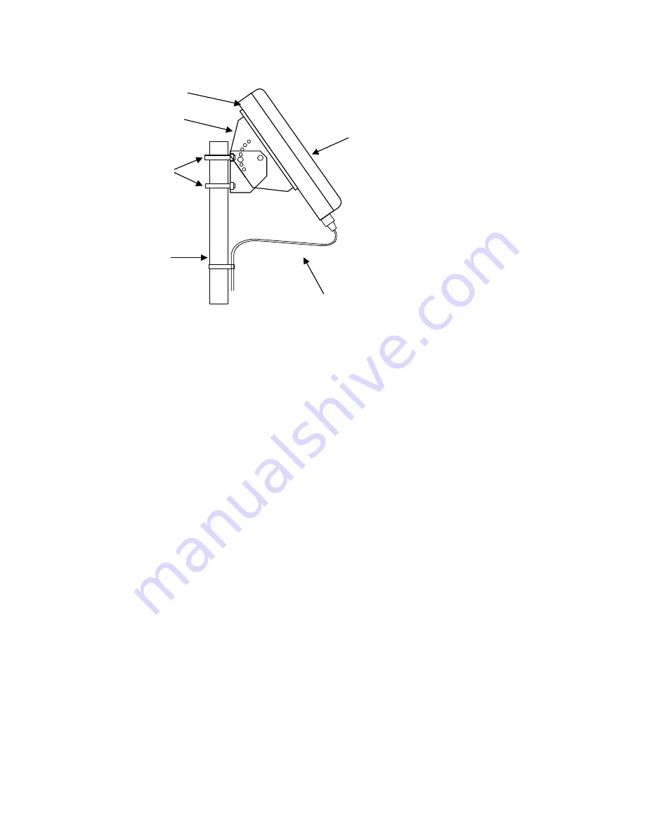
Interface Cable
Mounting
Bracket
Mounting
Pole
Clamps
SDT5000
Antenna
Figure 1. Initially aim the unit in the satellite direction, and tighten the bolts finger tight only. The
satellite is situated over the equator roughly in the center of North America. The view to the satellite
should be relatively unobstructed by trees, hills and man-made structures. Do not fully tighten the
bolts on the pole mount or the mounting bracket until after the installation procedure is complete.
Secure the interface cable to the pole with cable straps as shown or other suitable fasteners; ensure to
leave enough slack in the cable to allow the antenna to be aimed to the satellite.
Connect RTU to the SDT 5000 interface Cable.
Connect the ALARM and SWITCH conductors from the interface cable to the remote equipment
(optional). (See Appendix C for details).
Connect a VT100 compatible terminal or PC based terminal program to the SDT 5000 Unit Cable
Test Port (DB9) connector using an appropriate RS-232 cable and adapter. The VT100 terminal
should be configured as follows:
9600 baud, no parity, 8 data bits, 1 stop bit, full duplex, no flow control
Note: Protect the Test Port connector from physical damage or exposure to weather
conditions when it is not in use. The Test Port connector is protected with a cover plate. The
design of the cover plate allows the installer to completely loosen one screw (the screw
should remain attached to the cover plate by the gasket). The second screw should be
loosened only enough to allow the cover plate to swing to the side. When the test port is not
in use the cover plate must be securely fastened.
Connect the 12 Volt power supply or battery to the SDT 5000 via the interface cable conductors
(See Appendix B for details). With power applied and the ignition line is asserted (ignition line
connected to 12V or Switch J4 ‘on’) the SDT 5000 should start and the VT100 terminal will
display a number of status messages as shown below: (Information may vary dependant on the
firmware release):
Version 1.1, 03/24/06
Page 7


