39
11/00
F18 - 125
F18 - 125
F18 - 125
F18 - 125
F18 - 125cc / 150cc
cc / 150cc
cc / 150cc
cc / 150cc
cc / 150cc
CHECK OF THE VOLTAGE TO THE
CHECK OF THE VOLTAGE TO THE
CHECK OF THE VOLTAGE TO THE
CHECK OF THE VOLTAGE TO THE
CHECK OF THE VOLTAGE TO THE
HORN TERMINALS
HORN TERMINALS
HORN TERMINALS
HORN TERMINALS
HORN TERMINALS
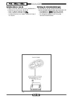
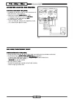
• Disconnect the terminals from the
horn and check the voltage (tester
(tester
(tester
(tester
(tester
DC 20V)
DC 20V)
DC 20V)
DC 20V)
DC 20V) (F. 26/a):
- Tester terminal (+): blue
blue
blue
blue
blue cable
terminal
- Tester terminal (-): orange
orange
orange
orange
orange cable
terminal
- Change-over switch key on “ON”
• Press the push button “HORN”:
-
Voltage 12 Volts: replace the
horn
-
No voltage: continue searching.
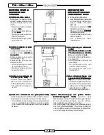
Check the voltage to the blue cable
Check the voltage to the blue cable
Check the voltage to the blue cable
Check the voltage to the blue cable
Check the voltage to the blue cable
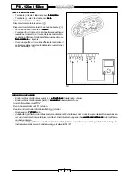
- Connect the tester (DC 20V)
(F. 26/b).
- Tester terminal (+): blue
blue
blue
blue
blue cable
terminal
- Tester terminal (-): grounded to
frame.
- Turn the key on “ON”.
- Voltage must be 12 Volt.
- Voltage = 0 blue cable broken.
Repair (see electric diagram).
- Voltage 12 Volt: orange cable
broken between the terminal, which
is connected to the horn and the
terminal, which is connected to the
9-way connector of the left
commutator.
Repair (see electric diagram).
CONTROL TENSION TERMINALES
CONTROL TENSION TERMINALES
CONTROL TENSION TERMINALES
CONTROL TENSION TERMINALES
CONTROL TENSION TERMINALES
CLAXON
CLAXON
CLAXON
CLAXON
CLAXON
• Desconectar los terminales del
claxon, y controlar la tensión (tester
(tester
(tester
(tester
(tester
DC 20V)
DC 20V)
DC 20V)
DC 20V)
DC 20V) (F. 26/a):
- Terminal (+) tester: terminal cable
azul
azul
azul
azul
azul
- Terminal (-) tester: terminal cable
naranja
naranja
naranja
naranja
naranja
- Llave conmutador en “ON”
• Apretar el botón “HORN”:
-
Tensión 12 volt: sustituir el claxon
-
Falta tensión: continuar la
búsqueda.
Controlar la tensión al cable azul
Controlar la tensión al cable azul
Controlar la tensión al cable azul
Controlar la tensión al cable azul
Controlar la tensión al cable azul
- Conectar el tester (DC 20V)
(F. 26/b).
- Terminal (+) tester: terminal cable
azul
azul
azul
azul
azul.
- Terminal (-) tester: en masa chasís.
- Situar la llave en “ON”.
- La tensión que resulte debe ser
de12 Volt.
- Tensión = 0 cable azul
interrumpido. Reparar (ver
esquema eléctrico).
- Tensión 12 Volt: cable naranja
interrumpido entre el terminal
conectado al claxon y terminal
conectado al conector de nueve
vías del conmutador izquierdo.
Reparar (ver esquema eléctrico).
CONTRÔLE TENSION COSSES
CONTRÔLE TENSION COSSES
CONTRÔLE TENSION COSSES
CONTRÔLE TENSION COSSES
CONTRÔLE TENSION COSSES
AVERTISSEUR
AVERTISSEUR
AVERTISSEUR
AVERTISSEUR
AVERTISSEUR
• Débrancher les cosses de
l’avertisseur, et contrôler la tension
(testeur CC 20V)
(testeur CC 20V)
(testeur CC 20V)
(testeur CC 20V)
(testeur CC 20V) (F. 26/a) :
- Borne (+) testeur : cosse câble
bleu
bleu
bleu
bleu
bleu
- Borne (-) testeur : cosse câble
orange
orange
orange
orange
orange
- Clef commutateur sur “ON”
• Appuyer sur la touche “HORN” :
- Tension 12 volts : changer
l’avertisseur
- Absence de tension : poursuivre
la recherche.
Contrôle de la tension au câble bleu
Contrôle de la tension au câble bleu
Contrôle de la tension au câble bleu
Contrôle de la tension au câble bleu
Contrôle de la tension au câble bleu
- Connecter le testeur (CC 20V)
(F. 26/b).
- Borne (+) testeur : cosse câble
bleu
bleu
bleu
bleu
bleu
- Borne (-) testeur : à la masse sur
châssis.
- Tourner la clef sur “ON”.
- La tension trouvée doit être de 12
Volts.
- Tension = 0 câble bleu interrompu.
Réparer (voir schéma électrique).
- Tension 12 Volts : câble orange
interrompu entre la cosse
introduite dans l’avertisseur et la
cosse introduite dans le
connecteur à neuf voies du
commutateur gauche.
Réparer (voir schéma électrique).
Содержание F18 WARRIOR
Страница 63: ...62 11 00 NOTES NOTES NOTES NOTES NOTES...


