59
11/00
F18 - 125
F18 - 125
F18 - 125
F18 - 125
F18 - 125cc / 150cc
cc / 150cc
cc / 150cc
cc / 150cc
cc / 150cc
B)
B)
B)
B)
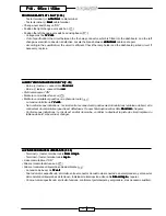
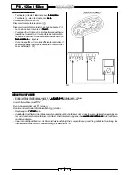
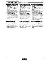
B) Check of the voltage to the 6-way
Check of the voltage to the 6-way
Check of the voltage to the 6-way
Check of the voltage to the 6-way
Check of the voltage to the 6-way
connector of the dashboard (te-
connector of the dashboard (te-
connector of the dashboard (te-
connector of the dashboard (te-
connector of the dashboard (te-
ster DC 20V)
ster DC 20V)
ster DC 20V)
ster DC 20V)
ster DC 20V)
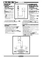
- Tester terminal (+): pink
pink
pink
pink
pink cable
terminal (F. 39)
(F. 39)
(F. 39)
(F. 39)
(F. 39)
- Tester terminal (-): black
black
black
black
black cable
terminal
• Change-over switch key on “ON”
• Light switch of the right change-over
switch positioned on
or
• Voltage must be 12 Volts
12 Volts
12 Volts
12 Volts
12 Volts.
-
According to the specification:
check the lamp and lamp holder
conditions. If they are in good
conditions, replace the dashboard.
-
Out of specification: continue
searching.
C)
C)
C)
C)
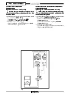
C) Check of the pink cable
Check of the pink cable
Check of the pink cable
Check of the pink cable
Check of the pink cable
continuity
continuity
continuity
continuity
continuity
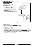
• Connect the tester (
tester (
tester (
tester (
tester (
Ω
Ω
Ω
Ω
Ω
x 1)
x 1)
x 1)
x 1)
x 1) between
the terminal, which is fitted into the
dashboard connector, and the
terminal, which is fitted into the right
change-over switch connector.
Locate the break and repair.
B)
B)
B)
B)
B) Control tensión al conector de
Control tensión al conector de
Control tensión al conector de
Control tensión al conector de
Control tensión al conector de
seis vías del salpicadero (tester
seis vías del salpicadero (tester
seis vías del salpicadero (tester
seis vías del salpicadero (tester
seis vías del salpicadero (tester
DC 20V)
DC 20V)
DC 20V)
DC 20V)
DC 20V)
- Terminal (+) tester: terminal cable
rosa (F. 39)
rosa (F. 39)
rosa (F. 39)
rosa (F. 39)
rosa (F. 39)
- Terminal (-) tester: terminal cable
negro
negro
negro
negro
negro
• Llave conmutador en “ON”.
• Interruptor luces conmutador
derecho en posición
o
• La tensión debe ser de 12 volt.
12 volt.
12 volt.
12 volt.
12 volt.
-
Como el valor especificado:
controlar el estado de la lámpara
y de los portalámpara. Si están en
buen estado, sustituir el
salpicadero.
-
Fuera del valor especificado:
continuar la búsqueda.
C)
C)
C)
C)
C) Control continuidad del cable
Control continuidad del cable
Control continuidad del cable
Control continuidad del cable
Control continuidad del cable
rosa
rosa
rosa
rosa
rosa
• Conectar el tester (
tester (
tester (
tester (
tester (
Ω
Ω
Ω
Ω
Ω
x 1)
x 1)
x 1)
x 1)
x 1) entre
terminal conectado en el conector
del salpicadero y terminal conectado
en el conector del conmutador
derecho. Individuar interrupción y
reparar.
B)
B)
B)
B)
B) Contrôle tension au connecteur
Contrôle tension au connecteur
Contrôle tension au connecteur
Contrôle tension au connecteur
Contrôle tension au connecteur
à six voies du tableau de bord
à six voies du tableau de bord
à six voies du tableau de bord
à six voies du tableau de bord
à six voies du tableau de bord
(testeur CC 20V)
(testeur CC 20V)
(testeur CC 20V)
(testeur CC 20V)
(testeur CC 20V)
- Borne (+) testeur : cosse câble
rose (F. 39)
rose (F. 39)
rose (F. 39)
rose (F. 39)
rose (F. 39)
- Borne (-) testeur : cosse câble
noir
noir
noir
noir
noir
• Clef démarreur sur “ON”.
• Interrupteur feux commutateur droit
en position
ou
• La tension doit être de 12 volts.
12 volts.
12 volts.
12 volts.
12 volts.
- Conforme aux indications :
contrôler l’état de l’ampoule et des
douilles. Si elles sont en bon état,
changer le tableau de bord.
- Non conforme aux indications :
poursuivre la recherche.
C)
C)
C)
C)
C) Contrôle de la continuité du
Contrôle de la continuité du
Contrôle de la continuité du
Contrôle de la continuité du
Contrôle de la continuité du
câble rose
câble rose
câble rose
câble rose
câble rose
• Brancher le testeur (
testeur (
testeur (
testeur (
testeur (
Ω
Ω
Ω
Ω
Ω
x 1)
x 1)
x 1)
x 1)
x 1) entre la
cosse introduite dans le connecteur
du tableau de bord et la cosse
introduite dans le connecteur du
commutateur droit. Trouver
l’interruption et réparer.
Содержание F18 WARRIOR
Страница 63: ...62 11 00 NOTES NOTES NOTES NOTES NOTES...

