(E)
17
MG10-P1 / MG10-P2
The settings described in this chapter concern the setting of the
parameters for initializing the main unit when the power is turned
on. The settings of the parameters which have been set are retained
even after the power has been turned off.
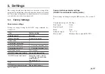
5-1. Factory Settings
Stored value settings
Settings are changed using the RS-232C setup command (see
section 5-4).
Item
Factory setting
Reference point
Not used
Measuring mode
Current value mode
Preset value
0
Comparator set number
1
Comparator upper limit
0
∗
For all set numbers 1 to 4
Comparator lower limit
0
∗
For all set numbers 1 to 4
Start/Hold function
Start function
RS-232C trigger input setting
Low-speed mode setting
RS-232C output data format
Measuring mode
+
Go/No
GO judgment result addition
mode (mode 3)
See section 6-1-3.
Unit
mm
RS-232C data transfer format
Separation by spaces
5. Settings
Communication parameter settings
(RS-232C communication setting switch)
These settings are changed using the DIP switches. (See section 5-
2)
Communication speed : 9600 bps
Data length
: 8 bits
Stop bit length
: 1 bit
Parity
: None
Delimiter output
: “
CR
”
+
“
LF
”
Flow control
: Hardware flow control (RTS, CTS)
Содержание MG10-P1
Страница 3: ...J 1 MG10 P1 MG10 P2...
Страница 4: ...2 J MG10 P1 MG10 P2 DC AC...
Страница 6: ...MG10 P1 MG10 P2 ii J Microsoft Windows Windows 7 35 8 36 8 1 36 8 2 37 8 3 37 9 38...
Страница 9: ...MG10 P1 MG10 P2 J 3 1 3 BCD DG DT DL DK PLC 16 RS 232C...
Страница 10: ...MG10 P1 MG10 P2 4 J 2 6 7 4 5 8 2 9 10 11 12 13 14 1 3...
Страница 12: ...MG10 P1 MG10 P2 6 J 3 3 1 16 1 2...
Страница 13: ...MG10 P1 MG10 P2 J 7 3 4 2 3 1 1 4 3 2 I F I F 1 1...
Страница 14: ...MG10 P1 MG10 P2 8 J 2 I F I F 3 1 3...
Страница 15: ...MG10 P1 MG10 P2 J 9 2 DIN DIN DIN 3 3 DIN DIN DIN 35 mm 1 DIN...
Страница 16: ...MG10 P1 MG10 P2 10 J 3 5 1 3 I O 3 GND 2 Vin DC 12 V 24 V 1 FG 2 3 3 4 1...
Страница 17: ...MG10 P1 MG10 P2 J 11 3 6 1 LZ61 CE08 RS 232C I F 3 7 1 RS 232C DZ252 RS 232C...
Страница 19: ...MG10 P1 MG10 P2 J 13 4 2 3 DK 1 1 mm 2 1 mm 3...
Страница 20: ...MG10 P1 MG10 P2 14 J 4 2 5 P P 4 RS 232C SETUP P CLOSE 1 mm RS 232C 1 4 2 4 0...
Страница 21: ...MG10 P1 MG10 P2 J 15 4 2 6 RS 232C MG30 B BCD 4 RS 232 NG U GO G GO G GO G NG L...
Страница 22: ...MG10 P1 MG10 P2 16 J ON P P OFF 4 2 7...
Страница 24: ...MG10 P1 MG10 P2 18 J 5 2 5 2 1 1 0 F...
Страница 28: ...MG10 P1 MG10 P2 22 J 7 ASCII ASCII ASCII OK 8 R...
Страница 32: ...MG10 P1 MG10 P2 26 J 6 RS 232C I O I F I F I F 4 2 3 OFF RS 232C I O...
Страница 40: ...MG10 P1 MG10 P2 34 J 6 2 3 RS 232C MIN 25 ms MIN 1 ms RS RS MIN 2 ms MAX 2 ms MIN 2 ms...
Страница 41: ...MG10 P1 MG10 P2 J 35 Error 3 5 E 1 00 Error 2 00NM Error 3 00NME Error 2 F 1 00 F0 0000 7 I O RS 232C 6 6...
Страница 44: ...MG10 P1 MG10 P2 38 J q 12 V 24 V w RS 232C MG10 MG10 e MG10 9 r MG10 t...
Страница 52: ...4 E MG10 P1 MG10 P2 6 7 4 5 8 2 9 10 11 12 13 14 1 3 2 Name and Function of Each Part...
Страница 94: ...4 G MG10 P1 MG10 P2 6 7 4 5 8 2 9 10 11 12 13 14 1 3 2 Teilebezeichnungen und Funktionen...
Страница 131: ...1 z q w x q w e r t c v b MG10 P1 MG10 P2...


