(E)
1
MG10-P1 / MG10-P2
1. Overview
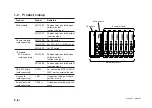
The MG10 main module combines counter modules and an I/F
module into a single unit that can output measurement data and
make various settings from a RS-232C port (standard feature) and
an I/O connector. The minimum configuration includes one main
module and one counter module; the maximum configuration
consists of one main module, 16 counter modules and one I/F
module. Furthermore, by connecting the units using a link cable,
up to 16 units can be connected (up to 64 counter modules can be
connected), and control can be exercised and data output from a
single RS-232C connector.
Counter modules are available for use with DK series, DG
∗∗
B
series, DL
∗∗
B/BR series, and DT series measuring units. In addition,
these counter modules can also be mixed and used in combination.
1-1. Features
•
Small size ideally suited for incorporation inside an electrical
parts panel
•
Construction that allows for installation on DIN rails (35 mm
DIN rail)
•
Expansion from 1 to 16 channels enabled by module
configuration
•
Connection of up to 64 channels possible using the link cables
•
Mixing and connection of any models in the DK series, DG
∗∗
B
series, DL
∗∗
B/BR series and DT series measuring unit for use
together
•
Input resolutions of 0.1
µ
m, 0.5
µ
m, 1
µ
m, 5
µ
m and 10
µ
m
supported
•
Measurement of maximum values, minimum values and peak-
to-peak values possible in addition to current values
•
Go/No Go judgment can be carried out by the comparator
function
•
Four different sets of comparator setting values can be set
•
Choice between two hold functions when the measuring unit is
retracted for work changes:
q
Latch function for temporarily holding the current values
w
Pause function for temporarily stopping the updating of the
maximum values, minimum values and peak-to-peak values
•
RS-232C interface provided as standard
•
BCD output enabled by connection of BCD module which is
sold separately
•
DC
+
12 to
+
24 V external power supply
Содержание MG10-P1
Страница 3: ...J 1 MG10 P1 MG10 P2...
Страница 4: ...2 J MG10 P1 MG10 P2 DC AC...
Страница 6: ...MG10 P1 MG10 P2 ii J Microsoft Windows Windows 7 35 8 36 8 1 36 8 2 37 8 3 37 9 38...
Страница 9: ...MG10 P1 MG10 P2 J 3 1 3 BCD DG DT DL DK PLC 16 RS 232C...
Страница 10: ...MG10 P1 MG10 P2 4 J 2 6 7 4 5 8 2 9 10 11 12 13 14 1 3...
Страница 12: ...MG10 P1 MG10 P2 6 J 3 3 1 16 1 2...
Страница 13: ...MG10 P1 MG10 P2 J 7 3 4 2 3 1 1 4 3 2 I F I F 1 1...
Страница 14: ...MG10 P1 MG10 P2 8 J 2 I F I F 3 1 3...
Страница 15: ...MG10 P1 MG10 P2 J 9 2 DIN DIN DIN 3 3 DIN DIN DIN 35 mm 1 DIN...
Страница 16: ...MG10 P1 MG10 P2 10 J 3 5 1 3 I O 3 GND 2 Vin DC 12 V 24 V 1 FG 2 3 3 4 1...
Страница 17: ...MG10 P1 MG10 P2 J 11 3 6 1 LZ61 CE08 RS 232C I F 3 7 1 RS 232C DZ252 RS 232C...
Страница 19: ...MG10 P1 MG10 P2 J 13 4 2 3 DK 1 1 mm 2 1 mm 3...
Страница 20: ...MG10 P1 MG10 P2 14 J 4 2 5 P P 4 RS 232C SETUP P CLOSE 1 mm RS 232C 1 4 2 4 0...
Страница 21: ...MG10 P1 MG10 P2 J 15 4 2 6 RS 232C MG30 B BCD 4 RS 232 NG U GO G GO G GO G NG L...
Страница 22: ...MG10 P1 MG10 P2 16 J ON P P OFF 4 2 7...
Страница 24: ...MG10 P1 MG10 P2 18 J 5 2 5 2 1 1 0 F...
Страница 28: ...MG10 P1 MG10 P2 22 J 7 ASCII ASCII ASCII OK 8 R...
Страница 32: ...MG10 P1 MG10 P2 26 J 6 RS 232C I O I F I F I F 4 2 3 OFF RS 232C I O...
Страница 40: ...MG10 P1 MG10 P2 34 J 6 2 3 RS 232C MIN 25 ms MIN 1 ms RS RS MIN 2 ms MAX 2 ms MIN 2 ms...
Страница 41: ...MG10 P1 MG10 P2 J 35 Error 3 5 E 1 00 Error 2 00NM Error 3 00NME Error 2 F 1 00 F0 0000 7 I O RS 232C 6 6...
Страница 44: ...MG10 P1 MG10 P2 38 J q 12 V 24 V w RS 232C MG10 MG10 e MG10 9 r MG10 t...
Страница 52: ...4 E MG10 P1 MG10 P2 6 7 4 5 8 2 9 10 11 12 13 14 1 3 2 Name and Function of Each Part...
Страница 94: ...4 G MG10 P1 MG10 P2 6 7 4 5 8 2 9 10 11 12 13 14 1 3 2 Teilebezeichnungen und Funktionen...
Страница 131: ...1 z q w x q w e r t c v b MG10 P1 MG10 P2...

