(G)
29
MG10-P1 / MG10-P2
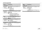
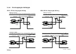
Kanal 0
Kanal 1
Kanal N
Begrenzungszeichen
[Beispiel]
Ausgabedaten Ausgabedaten
Ausgabedaten
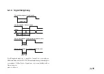
Zahlenwert:
Fixiert auf 8 Byte: Zeichen
+
oder
−
gefolgt von den Daten
(einschließlich Dezimalpunkt)
[Beispiel 1]
Für eine Auflösung von 0,1
µ
m
: “
−
99.9999” bis “
+
99.9999”
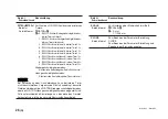
[Beispiel 2]
Für eine Auflösung von 10
µ
m
: “
−
9999.99” bis “
+
9999.99”
[Beispiel 3]
Im Falle eines Überlaufs wird die Zählung
fortgesetzt, aber das Anfangszeichen wechselt
zu “F.”
“
−
99.9999”
→
“
−
F0.0000”
→
“
−
F0.0001”
[Beispiel 4]
Wenn ein Alarm aufgetreten ist, erscheint
“Error”:
(“ ”, “ ”, “E”, “r”, “r”, “o”, “r”,“ ”)
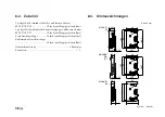
Datenseparateichen:
1 Byte “ “ (Leerstelle) oder 2 Byte “
CR
”
+
“
LF
”
Wahl mittels RS-232C-Befehl (Werkseinstellung: Leerstelle).
Begrenzer:
2 Byte “
CR
”
+
“
LF
” oder 1 Byte “
CR
”
Wahl mittels Kommunikations-Einstellschalter Nr.2 am
Hauptgerät.
OFF : “
CR
”
+
“
LF
” (Werkseinstellung)
ON : “
CR
”
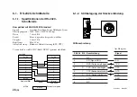
6-1-3. Kommunikationsformat
Kommunikationsdaten-Ausgabeformat
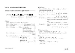
Kopf:
5 Byte (abhängig vom Kommunikationsmodus)
Byte 1 : Anfangszeichen ..................... Gerätenummer
0 bis F
Byte 2 : 2. Zeichen .............................. Kanalnummer
0 bis F
Byte 3 : 3. Zeichen ............ Modus Istwertmodus
: N
Maximalwertmodus
: A
Minimalwertmodus
: I
Spitze-Spitze-Wert-Modus : P
Byte 4 : 4. Zeichen .............................................. Gerät M (mm)
I (Zoll)
Byte 5 : 5. Zeichen Komparator-Beurteilungswert
.............................. Obergrenze NG
: U
Innerhalb des Bereichs
: G
Untergrenze NG
: L
Wenn ein Alarm aufgetreten ist : E
Содержание MG10-P1
Страница 3: ...J 1 MG10 P1 MG10 P2...
Страница 4: ...2 J MG10 P1 MG10 P2 DC AC...
Страница 6: ...MG10 P1 MG10 P2 ii J Microsoft Windows Windows 7 35 8 36 8 1 36 8 2 37 8 3 37 9 38...
Страница 9: ...MG10 P1 MG10 P2 J 3 1 3 BCD DG DT DL DK PLC 16 RS 232C...
Страница 10: ...MG10 P1 MG10 P2 4 J 2 6 7 4 5 8 2 9 10 11 12 13 14 1 3...
Страница 12: ...MG10 P1 MG10 P2 6 J 3 3 1 16 1 2...
Страница 13: ...MG10 P1 MG10 P2 J 7 3 4 2 3 1 1 4 3 2 I F I F 1 1...
Страница 14: ...MG10 P1 MG10 P2 8 J 2 I F I F 3 1 3...
Страница 15: ...MG10 P1 MG10 P2 J 9 2 DIN DIN DIN 3 3 DIN DIN DIN 35 mm 1 DIN...
Страница 16: ...MG10 P1 MG10 P2 10 J 3 5 1 3 I O 3 GND 2 Vin DC 12 V 24 V 1 FG 2 3 3 4 1...
Страница 17: ...MG10 P1 MG10 P2 J 11 3 6 1 LZ61 CE08 RS 232C I F 3 7 1 RS 232C DZ252 RS 232C...
Страница 19: ...MG10 P1 MG10 P2 J 13 4 2 3 DK 1 1 mm 2 1 mm 3...
Страница 20: ...MG10 P1 MG10 P2 14 J 4 2 5 P P 4 RS 232C SETUP P CLOSE 1 mm RS 232C 1 4 2 4 0...
Страница 21: ...MG10 P1 MG10 P2 J 15 4 2 6 RS 232C MG30 B BCD 4 RS 232 NG U GO G GO G GO G NG L...
Страница 22: ...MG10 P1 MG10 P2 16 J ON P P OFF 4 2 7...
Страница 24: ...MG10 P1 MG10 P2 18 J 5 2 5 2 1 1 0 F...
Страница 28: ...MG10 P1 MG10 P2 22 J 7 ASCII ASCII ASCII OK 8 R...
Страница 32: ...MG10 P1 MG10 P2 26 J 6 RS 232C I O I F I F I F 4 2 3 OFF RS 232C I O...
Страница 40: ...MG10 P1 MG10 P2 34 J 6 2 3 RS 232C MIN 25 ms MIN 1 ms RS RS MIN 2 ms MAX 2 ms MIN 2 ms...
Страница 41: ...MG10 P1 MG10 P2 J 35 Error 3 5 E 1 00 Error 2 00NM Error 3 00NME Error 2 F 1 00 F0 0000 7 I O RS 232C 6 6...
Страница 44: ...MG10 P1 MG10 P2 38 J q 12 V 24 V w RS 232C MG10 MG10 e MG10 9 r MG10 t...
Страница 52: ...4 E MG10 P1 MG10 P2 6 7 4 5 8 2 9 10 11 12 13 14 1 3 2 Name and Function of Each Part...
Страница 94: ...4 G MG10 P1 MG10 P2 6 7 4 5 8 2 9 10 11 12 13 14 1 3 2 Teilebezeichnungen und Funktionen...
Страница 131: ...1 z q w x q w e r t c v b MG10 P1 MG10 P2...

