MG10-P1 / MG10-P2
(E)
i
Contents
5. Settings ............................................. 17
5-1.
Factory Settings ............................................................ 17
5-2.
Main Module Settings ................................................... 18
5-2-1.
Unit Number Settings ............................... 18
5-2-2.
Communication Parameter Settings ......... 19
5-3.
Settings of Counter Modules Sold Separately .............. 20
5-3-1.
Counter Module Number
(Channel Number) Setting Switch ........... 20
5-3-2.
Measuring Unit Settings ........................... 20
5-4.
Changing the Factory Settings
(RS-232C Commands) .................................................. 21
5-4-1.
List of Setup Command ............................ 23
5-4-2.
Details of Command Settings ................... 23
6. Operation .......................................... 26
6-1.
RS-232C Interface ........................................................ 27
6-1-1.
RS-232C Interface Specifications ............ 27
6-1-2.
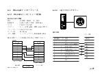
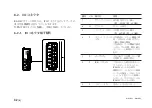
Connector Pin Assignment ....................... 27
6-1-3.
Communication Format ............................ 28
6-1-4.
Link Connection ....................................... 29
6-1-5.
Operation Commands ............................... 30
6-2.
I/O Connector ............................................................... 32
6-2-1.
I/O Connector Pin Assignment ................ 32
6-2-2.
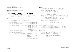
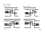
Input/Output Circuits ................................ 33
6-2-3.
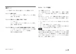
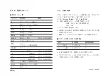
Signal Timing ........................................... 34
1. Overview ............................................. 1
1-1.
Features ........................................................................... 1
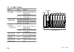
1-2.
Product Lineup ................................................................ 2
1-3.
System Configuration ..................................................... 3
2. Name and Function of Each Part ...... 4
3. Connections and Installation ............ 6
3-1.
Connecting the Counter Modules ................................... 6
3-2.
Connecting the I/F Module ............................................. 7
3-3.
Installing the Unit on the DIN Rails ............................... 9
3-4.
Connecting the Measuring Units .................................. 10
3-5.
Connecting the Power Connector ................................. 10
3-6.
Link Connections .......................................................... 11
3-7.
Connection to the Host Unit ......................................... 11
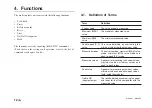
4. Functions .......................................... 12
4-1.
Definition of Terms ...................................................... 12
4-2.
Details of Functions ...................................................... 13
4-2-1.
Peak-hold .................................................. 13
4-2-2.
Preset ......................................................... 13
4-2-3.
Reference Point ........................................ 13
4-2-4.
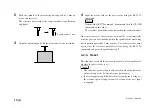
Reset .......................................................... 14
4-2-5.
Start ........................................................... 15
4-2-6.
Go/No GO Judgment (Comparator) ......... 15
4-2-7.
Hold .......................................................... 16
Содержание MG10-P1
Страница 3: ...J 1 MG10 P1 MG10 P2...
Страница 4: ...2 J MG10 P1 MG10 P2 DC AC...
Страница 6: ...MG10 P1 MG10 P2 ii J Microsoft Windows Windows 7 35 8 36 8 1 36 8 2 37 8 3 37 9 38...
Страница 9: ...MG10 P1 MG10 P2 J 3 1 3 BCD DG DT DL DK PLC 16 RS 232C...
Страница 10: ...MG10 P1 MG10 P2 4 J 2 6 7 4 5 8 2 9 10 11 12 13 14 1 3...
Страница 12: ...MG10 P1 MG10 P2 6 J 3 3 1 16 1 2...
Страница 13: ...MG10 P1 MG10 P2 J 7 3 4 2 3 1 1 4 3 2 I F I F 1 1...
Страница 14: ...MG10 P1 MG10 P2 8 J 2 I F I F 3 1 3...
Страница 15: ...MG10 P1 MG10 P2 J 9 2 DIN DIN DIN 3 3 DIN DIN DIN 35 mm 1 DIN...
Страница 16: ...MG10 P1 MG10 P2 10 J 3 5 1 3 I O 3 GND 2 Vin DC 12 V 24 V 1 FG 2 3 3 4 1...
Страница 17: ...MG10 P1 MG10 P2 J 11 3 6 1 LZ61 CE08 RS 232C I F 3 7 1 RS 232C DZ252 RS 232C...
Страница 19: ...MG10 P1 MG10 P2 J 13 4 2 3 DK 1 1 mm 2 1 mm 3...
Страница 20: ...MG10 P1 MG10 P2 14 J 4 2 5 P P 4 RS 232C SETUP P CLOSE 1 mm RS 232C 1 4 2 4 0...
Страница 21: ...MG10 P1 MG10 P2 J 15 4 2 6 RS 232C MG30 B BCD 4 RS 232 NG U GO G GO G GO G NG L...
Страница 22: ...MG10 P1 MG10 P2 16 J ON P P OFF 4 2 7...
Страница 24: ...MG10 P1 MG10 P2 18 J 5 2 5 2 1 1 0 F...
Страница 28: ...MG10 P1 MG10 P2 22 J 7 ASCII ASCII ASCII OK 8 R...
Страница 32: ...MG10 P1 MG10 P2 26 J 6 RS 232C I O I F I F I F 4 2 3 OFF RS 232C I O...
Страница 40: ...MG10 P1 MG10 P2 34 J 6 2 3 RS 232C MIN 25 ms MIN 1 ms RS RS MIN 2 ms MAX 2 ms MIN 2 ms...
Страница 41: ...MG10 P1 MG10 P2 J 35 Error 3 5 E 1 00 Error 2 00NM Error 3 00NME Error 2 F 1 00 F0 0000 7 I O RS 232C 6 6...
Страница 44: ...MG10 P1 MG10 P2 38 J q 12 V 24 V w RS 232C MG10 MG10 e MG10 9 r MG10 t...
Страница 52: ...4 E MG10 P1 MG10 P2 6 7 4 5 8 2 9 10 11 12 13 14 1 3 2 Name and Function of Each Part...
Страница 94: ...4 G MG10 P1 MG10 P2 6 7 4 5 8 2 9 10 11 12 13 14 1 3 2 Teilebezeichnungen und Funktionen...
Страница 131: ...1 z q w x q w e r t c v b MG10 P1 MG10 P2...

