(E)
21
MG10-P1 / MG10-P2
2
Click (execute) “Start”
→
“All Programs”
→
“Accessories”
→
“Communications”
→
“HyperTerminal”.
∗
If “Communications” and “HyperTerminal” cannot be found,
click “Start”
→
“Control Panel”
→
“Add and Remove
Programs”, install HyperTerminal, and start over from the
beginning. (See the Windows Help manual for details.)
3
Double-click (execute) “Hypertrm.exe”.
4
Enter “MG10” for the name and click OK.
(An optional name can also be entered. A shortcut is created
with this name.)
5
The “Connection Setup” window opens.
Select “Direct to Com1” for “Connection Method” in this
window.
6
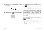
Set the baud rate and other settings to match the MG10 settings
under “COM1 Properties”.
Select “Hardware” (use RTS and CTS signals) for the flow
control.
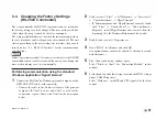
5-4. Changing the Factory Settings
(RS-232C Commands)
The setup commands for RS-232C communication are used when
the factory settings are to be changed. The new settings will take
effect when the setup is ended by the close command.
The settings established here are stored in the internal memory where
they are retained even after the power has been turned off. The unit
starts up according to the new settings the next time the power is
turned on. See “6-1. RS-232C Interface” for the communication
specifications.
It takes a maximum of about 3 seconds to save data after the CLOSE
command has been sent. Never turn off the unit’s power during this
time as the unit may cease to start normally.
Performing communication using the standard
Windows application “HyperTerminal”
1
Connect the MG10 and a Windows personal computer with a
DZ252 RS-232C cable (sold separately).
∗
Connect the cable to the Com1 serial port of the personal
computer. If Com1 is in use and Com2 is used for the
connection, replace Com1 with Com2 in the description
below.
Содержание MG10-P1
Страница 3: ...J 1 MG10 P1 MG10 P2...
Страница 4: ...2 J MG10 P1 MG10 P2 DC AC...
Страница 6: ...MG10 P1 MG10 P2 ii J Microsoft Windows Windows 7 35 8 36 8 1 36 8 2 37 8 3 37 9 38...
Страница 9: ...MG10 P1 MG10 P2 J 3 1 3 BCD DG DT DL DK PLC 16 RS 232C...
Страница 10: ...MG10 P1 MG10 P2 4 J 2 6 7 4 5 8 2 9 10 11 12 13 14 1 3...
Страница 12: ...MG10 P1 MG10 P2 6 J 3 3 1 16 1 2...
Страница 13: ...MG10 P1 MG10 P2 J 7 3 4 2 3 1 1 4 3 2 I F I F 1 1...
Страница 14: ...MG10 P1 MG10 P2 8 J 2 I F I F 3 1 3...
Страница 15: ...MG10 P1 MG10 P2 J 9 2 DIN DIN DIN 3 3 DIN DIN DIN 35 mm 1 DIN...
Страница 16: ...MG10 P1 MG10 P2 10 J 3 5 1 3 I O 3 GND 2 Vin DC 12 V 24 V 1 FG 2 3 3 4 1...
Страница 17: ...MG10 P1 MG10 P2 J 11 3 6 1 LZ61 CE08 RS 232C I F 3 7 1 RS 232C DZ252 RS 232C...
Страница 19: ...MG10 P1 MG10 P2 J 13 4 2 3 DK 1 1 mm 2 1 mm 3...
Страница 20: ...MG10 P1 MG10 P2 14 J 4 2 5 P P 4 RS 232C SETUP P CLOSE 1 mm RS 232C 1 4 2 4 0...
Страница 21: ...MG10 P1 MG10 P2 J 15 4 2 6 RS 232C MG30 B BCD 4 RS 232 NG U GO G GO G GO G NG L...
Страница 22: ...MG10 P1 MG10 P2 16 J ON P P OFF 4 2 7...
Страница 24: ...MG10 P1 MG10 P2 18 J 5 2 5 2 1 1 0 F...
Страница 28: ...MG10 P1 MG10 P2 22 J 7 ASCII ASCII ASCII OK 8 R...
Страница 32: ...MG10 P1 MG10 P2 26 J 6 RS 232C I O I F I F I F 4 2 3 OFF RS 232C I O...
Страница 40: ...MG10 P1 MG10 P2 34 J 6 2 3 RS 232C MIN 25 ms MIN 1 ms RS RS MIN 2 ms MAX 2 ms MIN 2 ms...
Страница 41: ...MG10 P1 MG10 P2 J 35 Error 3 5 E 1 00 Error 2 00NM Error 3 00NME Error 2 F 1 00 F0 0000 7 I O RS 232C 6 6...
Страница 44: ...MG10 P1 MG10 P2 38 J q 12 V 24 V w RS 232C MG10 MG10 e MG10 9 r MG10 t...
Страница 52: ...4 E MG10 P1 MG10 P2 6 7 4 5 8 2 9 10 11 12 13 14 1 3 2 Name and Function of Each Part...
Страница 94: ...4 G MG10 P1 MG10 P2 6 7 4 5 8 2 9 10 11 12 13 14 1 3 2 Teilebezeichnungen und Funktionen...
Страница 131: ...1 z q w x q w e r t c v b MG10 P1 MG10 P2...


