(E)
29
MG10-P1 / MG10-P2
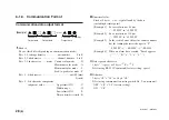
Communication modes
There are three modes each with a different header output.
Mode 1: Normal data output
Header consisting of 2 bytes (unit number
+
channel
number)
[Example] “00
−
09.9999”
Mode 2: Data output with measuring mode information
added
Header consisting of 4 bytes
(unit number
+
channel number
+
mode
+
unit)
[Example] “00NM
−
09.9999”
Mode 3: Data output with measuring mode and Go/No
Go judgment result information added
Header consisting of 5 bytes (unit number
+
channel
number
+
mode
+
unit
+
comparator judgment value)
[Example] “00NMG
−
09.9999”
6-1-4. Link Connection
Formats used during link connection
The data is output in the specified communication format (see
section 6-1-3) beginning from the highest order unit regardless of
the unit numbers which have been set.
The highest order unit is the unit connected to the host unit (PC or
PLC), and the lower order units are ranked according to the link
connection order from the highest order unit.
•
The data of each unit is separated by delimiters, and output.
•
No commands are used specifically for link connections.
•
When extending the link cable (LZ61), use a cable length of
10 m or less.
When using a link connection, be sure to use all the same commu-
nication settings (except for the RS-232C communication setup
switch SW1 master setting) and RS-TRG mode (high-speed/low-
speed) parameter settings. Normal communications are impossible
when the settings for each unit differ.
Содержание MG10-P1
Страница 3: ...J 1 MG10 P1 MG10 P2...
Страница 4: ...2 J MG10 P1 MG10 P2 DC AC...
Страница 6: ...MG10 P1 MG10 P2 ii J Microsoft Windows Windows 7 35 8 36 8 1 36 8 2 37 8 3 37 9 38...
Страница 9: ...MG10 P1 MG10 P2 J 3 1 3 BCD DG DT DL DK PLC 16 RS 232C...
Страница 10: ...MG10 P1 MG10 P2 4 J 2 6 7 4 5 8 2 9 10 11 12 13 14 1 3...
Страница 12: ...MG10 P1 MG10 P2 6 J 3 3 1 16 1 2...
Страница 13: ...MG10 P1 MG10 P2 J 7 3 4 2 3 1 1 4 3 2 I F I F 1 1...
Страница 14: ...MG10 P1 MG10 P2 8 J 2 I F I F 3 1 3...
Страница 15: ...MG10 P1 MG10 P2 J 9 2 DIN DIN DIN 3 3 DIN DIN DIN 35 mm 1 DIN...
Страница 16: ...MG10 P1 MG10 P2 10 J 3 5 1 3 I O 3 GND 2 Vin DC 12 V 24 V 1 FG 2 3 3 4 1...
Страница 17: ...MG10 P1 MG10 P2 J 11 3 6 1 LZ61 CE08 RS 232C I F 3 7 1 RS 232C DZ252 RS 232C...
Страница 19: ...MG10 P1 MG10 P2 J 13 4 2 3 DK 1 1 mm 2 1 mm 3...
Страница 20: ...MG10 P1 MG10 P2 14 J 4 2 5 P P 4 RS 232C SETUP P CLOSE 1 mm RS 232C 1 4 2 4 0...
Страница 21: ...MG10 P1 MG10 P2 J 15 4 2 6 RS 232C MG30 B BCD 4 RS 232 NG U GO G GO G GO G NG L...
Страница 22: ...MG10 P1 MG10 P2 16 J ON P P OFF 4 2 7...
Страница 24: ...MG10 P1 MG10 P2 18 J 5 2 5 2 1 1 0 F...
Страница 28: ...MG10 P1 MG10 P2 22 J 7 ASCII ASCII ASCII OK 8 R...
Страница 32: ...MG10 P1 MG10 P2 26 J 6 RS 232C I O I F I F I F 4 2 3 OFF RS 232C I O...
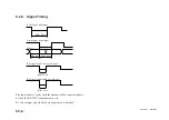
Страница 40: ...MG10 P1 MG10 P2 34 J 6 2 3 RS 232C MIN 25 ms MIN 1 ms RS RS MIN 2 ms MAX 2 ms MIN 2 ms...
Страница 41: ...MG10 P1 MG10 P2 J 35 Error 3 5 E 1 00 Error 2 00NM Error 3 00NME Error 2 F 1 00 F0 0000 7 I O RS 232C 6 6...
Страница 44: ...MG10 P1 MG10 P2 38 J q 12 V 24 V w RS 232C MG10 MG10 e MG10 9 r MG10 t...
Страница 52: ...4 E MG10 P1 MG10 P2 6 7 4 5 8 2 9 10 11 12 13 14 1 3 2 Name and Function of Each Part...
Страница 94: ...4 G MG10 P1 MG10 P2 6 7 4 5 8 2 9 10 11 12 13 14 1 3 2 Teilebezeichnungen und Funktionen...
Страница 131: ...1 z q w x q w e r t c v b MG10 P1 MG10 P2...


