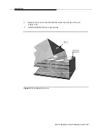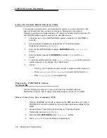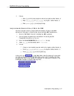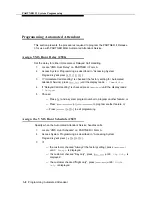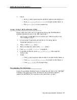
Installation
4.
5.
6.
7.
8.
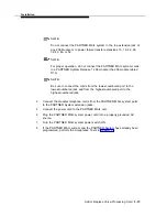
NOTE:
Do not connect the PARTNER MAIL system to the top extension jack of
any 206 Module or to power failure transfer extensions 10, 16, 22, 28,
34, 40, 46, or 52.
NOTE:
For proper operation, do not connect the PARTNER MAIL system cords
to a PARTNER System Release 1 206 module (the 206 module Iabled
R1.0).
NOTE:
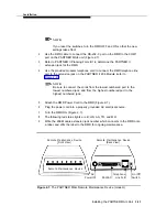
Be sure to connect the cords from the lowest-numbered port to the
lowest-numbered jack and from the highest-numbered port to the
highest-numbered jack.
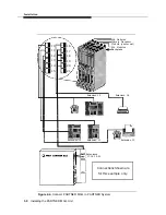
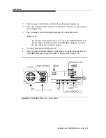
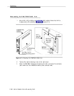
Connect the modular telephone cords from the PARTNER MAIL system ports
to the PARTNER System extension jacks.
Connect the power cord to the PARTNER MAIL unit.
Plug the PARTNER MAIL system power cord into a properly grounded AC
source.
Turn the PARTNER MAIL system power switch ON.
If the PARTNER MAIL system and the PARTNER System have already been
programmed, perform the Acceptance Tests in Chapter 5.
Add or Replace Voice-Processing Card
2-19
Содержание PARTNER MAIL
Страница 179: ...AT T 585 322 101 Graphics AT T 1988...

