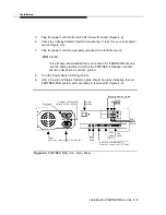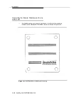
Installation
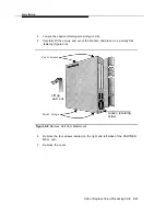
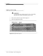
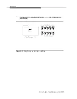
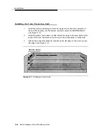
2.
3.
4.
5.
6.
7.
8.
9.
NOTE:
If you reset the switches, turn the RMD OFF and ON so that the new
settings take effect.
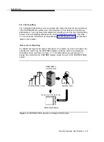
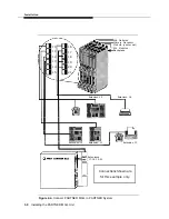
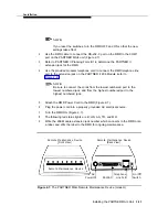
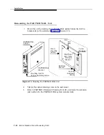
Use the RMD cable to connect the RS-232-C port on the RMD to the COM1
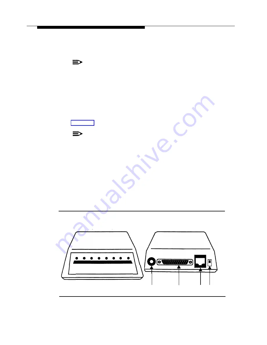
port on the PARTNER MAIL unit (Figure 2-7).
Refer to PARTNER II Planning Form B1 to determine the PARTNER II
extension jack for the RMD.
Use the provided modular telephone cord to connect the RMD telephone line
port to the extension jack on the PARTNER II 206 Module (refer to
NOTE:
Be sure to connect the cords from the lowest numbered port to the
lowest numbered jack, and from the highest numbered port to the
highest numbered jack.
Attach the RMD Power Cord to the RMD (Figure 2-7).
Plug the power cord into a properly grounded AC electrical source.
Turn the RMD ON (Figure 2-7).
The following red status lights are lit: HS, AA, TR, and MR.
Write the 206 Module extension jack number which connects to the RMD onto
a label, and affix the label to the RMD for ongoing maintenance.
Remote Maintenance Device
Remote Maintenance Device
(Front View)
(Back View)
Remote Maintenance Device
AC
Telephone
On/Off
Power IN
RS 232-C
Line Port
Switch
Figure 2-7. The PARTNER MAIL Remote Maintenance Device (modem)
Installing the PARTNER MAIL Unit
2-11
Содержание PARTNER MAIL
Страница 179: ...AT T 585 322 101 Graphics AT T 1988...

