586
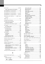
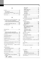
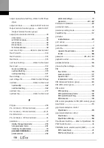
D
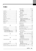
damper .............................................................................................. 211
Damper Err Trip ..................... Refer to
Damper Err Trip
damper operation .................................................................... 211
damper open delay time .................................. 211
DB resistor
braking resistor circuit ....................................... 357
DB Warn %ED .................................................. 357
DB Warn %ED .................................................................. 357, 558
DC braking after start ............................................................ 141
DC braking after stop ............................................................ 144
DC braking frequency ........................................................... 144
DC link voltage ........................................................................... 159
Dec valve ramping ................................................................... 224
deceleration stop ......................................................................... 84
delta wiring ....................................................................................... 42
derating ................................................................................ 272, 590
digital output................................................................................ 323
display ................................................................................................... 55
command source ................................................ 55
display mode table .............................................. 61
display modes ..................................................... 60
frequency reference ............................................ 55
operation mode ................................................... 55
rotational direction ............................................... 55
disposal ................................................................................. 568, 576
draw operation ........................................................................... 158
Drive group........................... Refer to DRV (Drive group)
DRV (Drive function group) ................................................. 62
DRV (Drive group) .................................................................... 439
dwell operation ........................................................................... 174
Acc/Dec dewel frequency ................................ 174
acceleration dwell ............................................. 174
deceleration dwell ............................................. 174
dynamic braking (DB) resistor configuration....... 357
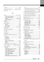
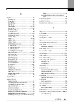
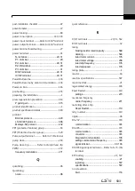
E
earth leakage breaker............................................................ 565
Easy
Start On ............................................................................................ 286
EEP Rom Empty.......................................................................... 278
EG terminal ....................................................................................... 39
electronic thermal overheating protection (ETH)
.......................................................................................................... 337
EMC filter ............................................................................................ 42
asymmetric power source ..................................42
disabling .................................................. 42, 44, 45
enable ...................................................................44
enabling ......................................................... 44, 45
emergency stop fault trip .................................Refer to
BX
Enclosed Type 1 ......................................................................... 582
energy saving ............................................................................... 216
energy saving operation ..................................................... 263
automatic energy saving operation................. 264
manual energy saving operation..................... 263
EPID (EPID control) group ..................................................... 62
EPID (External PID function group) ............................. 495
EPID control
external PID ...................................................... 200
EPID control group ..................................................................... 62
ETH .................Refer to
electronic thermal overheating
protection (ETH)
E-Thermal ........................................................................................ 554
Exception Date ............................................................................ 242
Exhaust Fan (MC3) ................................................................... 541
external 24V power terminal.... Refer to 24 terminal
External Trip ................................................................................... 555
external trip signal .................................................................... 351
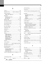
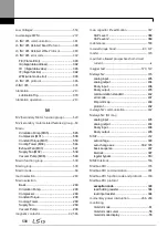
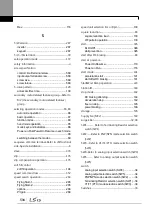
F
falut trips .......................................................................................... 553
fan life estimation ..................................................................... 368
fan replacement level ....................................... 369
fan time .............................................................. 369
fan operation warning .......................................................... 371
fan replacement warning .................................................... 558
Fan Trip .................................................................................. 361, 555
Fan Warning ...................................................................... 361, 557
fatal ...................................................................................................... 553
Содержание H100
Страница 14: ......
Страница 18: ...Preparing the Installation 4 37 90 kW 3 Phase ...
Страница 27: ...Preparing the Installation 13 ...
Страница 47: ...33 Installing the Inverter ...
Страница 48: ...Installing the Inverter 34 Input and Output Control Terminal Block Wiring Diagram ...
Страница 61: ...47 Installing the Inverter ...
Страница 71: ...Learning to Perform Basic Operations 57 ...
Страница 88: ...Learning to Perform Basic Operations 74 ...
Страница 103: ...89 Learning Basic Features Code Description V1 Quantizing ...
Страница 120: ...Learning Basic Features 106 Grou p Cod e Name LCD Display Parameter Setting Setting Range Unit Prev ...
Страница 129: ...115 Learning Basic Features ...
Страница 140: ...Learning Basic Features 126 ...
Страница 148: ...Learning Basic Features 134 ...
Страница 171: ...157 Learning Advanced Features Deceleration dwell operation ...
Страница 183: ...169 Learning Advanced Features ...
Страница 184: ...Learning Advanced Features 170 PID Command Block ...
Страница 185: ...171 Learning Advanced Features PID Feedback Block ...
Страница 186: ...Learning Advanced Features 172 PID Output Block ...
Страница 187: ...173 Learning Advanced Features PID Output Mode Block ...
Страница 197: ...183 Learning Advanced Features ...
Страница 201: ...187 Learning Advanced Features Code Description 100 EPID1 Control block ...
Страница 202: ...Learning Advanced Features 188 EPID2 Control block ...
Страница 237: ...223 Learning Advanced Features Time Period Schedule AP3 38 Except3 Day 01 01 ...
Страница 244: ...Learning Advanced Features 230 ...
Страница 259: ...245 Learning Advanced Features Code Description Code Description Volt ...
Страница 362: ...Learning Protection Features 348 ...
Страница 415: ...401 RS 485 Communication Features Item Standards Parity check None ...
Страница 524: ...Table of Functions 510 ...
Страница 533: ...Table of Functions 519 ...
Страница 547: ...533 Troubleshooting ...
Страница 564: ...Technical Specification 550 11 3 External Dimensions IP 20 Type 0 75 30 kW 3 phase 37 90 kW 3 phase ...
Страница 585: ...Technical Specification 571 ...
Страница 594: ...580 ...
Страница 595: ...581 ...
Страница 596: ...582 ...


