Chapter 4 CPU Specifications
XBC E-Type Main Unit
4-6
Ver. 1
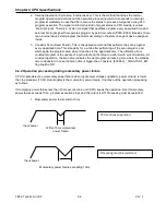
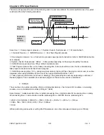
2. Interrupt operation (Cycle time, Internal device). This is the method that stops the normal
program operation and carries out the operation processing which corresponds to interrupt
program immediately in case that there occurs the status to process emergently during PLC
program execution. The signal to inform this kind of urgent status to CPU module is called
‘interrupt signal’. There is a Cycle time signal that operates program every appointed time and
external interrupt signal that operates program by external contact (P000~P003). Besides, there
is an internal device start program that starts according to the state change of device assigned
inside.
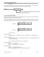
3. Constant Scan (Fixed Period). This is the operation method that performs the scan program
every appointed time. This stands by for a while after performing all the scan program, and
starts again the program scan when it reaches to the appointed time. The difference from
constant program is the update of input/output and the thing to perform with synchronization. At
constant operation, the scan time indicates the net program processing time where the standby
time is deducted. In case that scan time is bigger than ‘constant’, [F0005C] ‘_CONSTANT_ER’
flag shall be ‘ON’.
4.4.2 Operation processing during momentary power failure
CPU module detects a momentary power failure when input power voltage supplied to power module is lower
than the standard. If CPU module detects the momentary power failure, it carries out the operation processing
as follows.
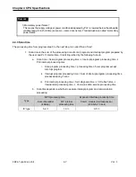
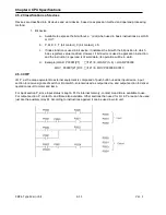
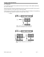
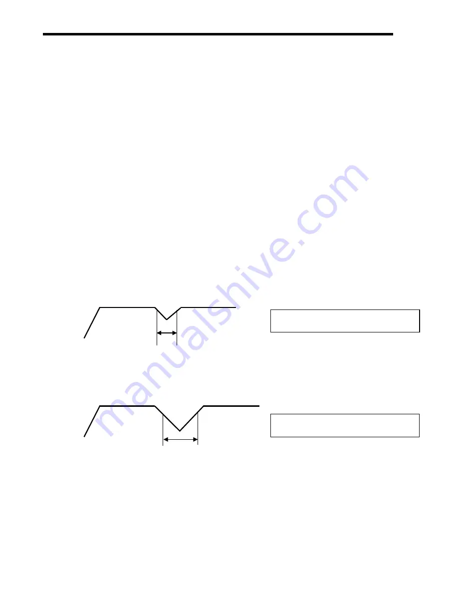
If momentary power failure less than 10ms occurs, main unit (CPU) keeps the operation. But, if momentary
power failure exceeds 10
㎳
, program execution stops and the output is Off. Processing must be restarted.
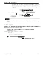
1. Momentary power failure within 10ms
Input power
Within 10ms momentary
power failure
Momentary power failure exceeding 10ms
Input power
CPU continues operation.
Processing must be restarted.
Содержание XBC-DN10E
Страница 1: ......
Страница 10: ...Table of Contents Table of Contents 6 10 10 CLEAR ALL PLC 29...
Страница 52: ...Chapter 3 Installation and Wiring XBC E Type Main Unit 3 24 Ver 1 3 7 2 XBC DR10E 4 point relay output...
Страница 54: ...Chapter 3 Installation and Wiring XBC E Type Main Unit 3 26 Ver 1 3 7 3 XBC DN10E 4 point transistor output...
Страница 56: ...Chapter 3 Installation and Wiring XBC E Type Main Unit 3 28 Ver 1 3 7 4 XBC DR14E 6 point relay output...
Страница 58: ...Chapter 3 Installation and Wiring XBC E Type Main Unit 3 30 Ver 1 3 7 5 XBC DN14E 6 point transistor output...
Страница 60: ...Chapter 3 Installation and Wiring XBC E Type Main Unit 3 32 Ver 1 3 7 6 XBC DR20E 8 point relay output...
Страница 62: ...Chapter 3 Installation and Wiring XBC E Type Main Unit 3 34 Ver 1 3 7 7 XBC DN20E 8 point transistor output...
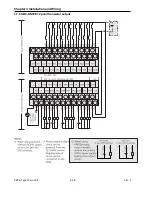
Страница 64: ...Chapter 3 Installation and Wiring XBC E Type Main Unit 3 36 Ver 1 3 7 8 XBC DR30E 12 point relay output...
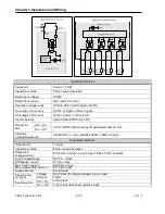
Страница 66: ...Chapter 3 Installation and Wiring XBC E Type Main Unit 3 38 Ver 1 3 7 9 XBC DN30E 12 point transistor output...


