Chapter 2 Quick Start Guide
XBC E-Type Main Unit
2-7
Ver. 1
2.4 Installation and Wiring of PLC
2.4.1 Connect Power Wiring
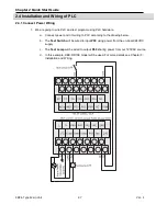
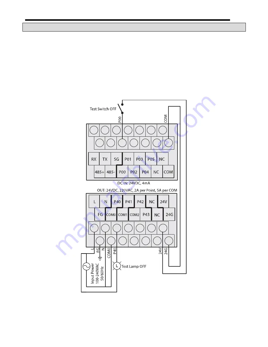
1. We are going to wire PLC and test program using PLC hardware.
a. Connect power and I/O wiring to PLC according to the drawing below.
b. The
Test Switch
will be wired to input
P00
using power from the on-board 24VDC
supply.
c. The
Test Lamp
will be wired to output
P40
sharing power from our 120VAC source.
d. In this example, XBC-DR10E model will be used. For more details see Chapter 3:
Installation and Wiring.
Содержание XBC-DN10E
Страница 1: ......
Страница 10: ...Table of Contents Table of Contents 6 10 10 CLEAR ALL PLC 29...
Страница 52: ...Chapter 3 Installation and Wiring XBC E Type Main Unit 3 24 Ver 1 3 7 2 XBC DR10E 4 point relay output...
Страница 54: ...Chapter 3 Installation and Wiring XBC E Type Main Unit 3 26 Ver 1 3 7 3 XBC DN10E 4 point transistor output...
Страница 56: ...Chapter 3 Installation and Wiring XBC E Type Main Unit 3 28 Ver 1 3 7 4 XBC DR14E 6 point relay output...
Страница 58: ...Chapter 3 Installation and Wiring XBC E Type Main Unit 3 30 Ver 1 3 7 5 XBC DN14E 6 point transistor output...
Страница 60: ...Chapter 3 Installation and Wiring XBC E Type Main Unit 3 32 Ver 1 3 7 6 XBC DR20E 8 point relay output...
Страница 62: ...Chapter 3 Installation and Wiring XBC E Type Main Unit 3 34 Ver 1 3 7 7 XBC DN20E 8 point transistor output...
Страница 64: ...Chapter 3 Installation and Wiring XBC E Type Main Unit 3 36 Ver 1 3 7 8 XBC DR30E 12 point relay output...
Страница 66: ...Chapter 3 Installation and Wiring XBC E Type Main Unit 3 38 Ver 1 3 7 9 XBC DN30E 12 point transistor output...


