Chapter 6 Instruction Details
XBC E-Type Main Unit
6-306
Ver. 1
6.44.2 FRST
Instruction
Area Available
Step
Flag
P M K
F
L
T
C
S
Z D.x R.x
Con
st.
U
N
D
R
Error
(F110)
Zero
(F111)
Carry
(F112)
FRST
D
-
-
-
O
-
-
-
-
-
-
-
-
-
-
-
-
2
-
-
-
Operand
Description
Data Size
D
F10240 ~ F2047F area in F area
BIT
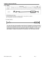
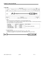
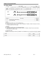
1) FRST
Used to reset the bit of F10240~F2047F in F area of Special Relay area.
It is not neccesary to use the FRST instruction because the bit of F10240 ~ F10243 area resets after 1
Scan automatically even if the bit becomes Set.
Flag name
Data size
Contact point
Reset Operation
_RTC_WR
BIT
F10240
Area of Reset automatically
_SCAN_WR
BIT
F10241
_CHK_ANC_ERR
BIT
F10242
_CHK_ANC_WAR
BIT
F10243
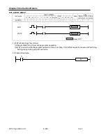
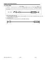
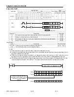
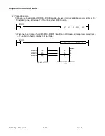
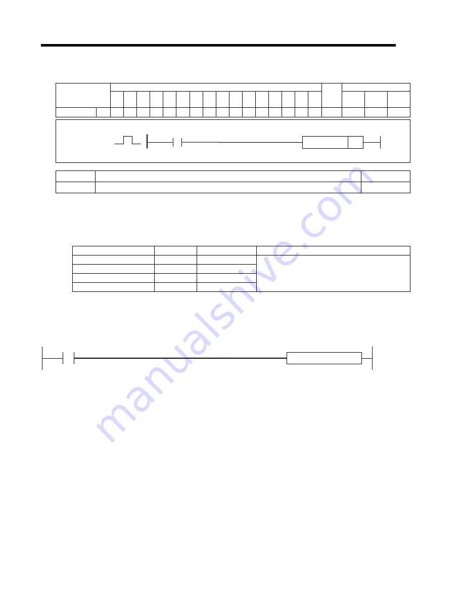
2) Program Example
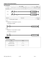
Reset the No.3 bit of external Warning information area (_ANC_WAR)
If P00000 is changed to On, number 3 bit of _ANC_WAR(F1027) is changed to Reset.
FRST F10272
P00000
FRST
FRST
D
Содержание XBC-DN10E
Страница 1: ......
Страница 10: ...Table of Contents Table of Contents 6 10 10 CLEAR ALL PLC 29...
Страница 52: ...Chapter 3 Installation and Wiring XBC E Type Main Unit 3 24 Ver 1 3 7 2 XBC DR10E 4 point relay output...
Страница 54: ...Chapter 3 Installation and Wiring XBC E Type Main Unit 3 26 Ver 1 3 7 3 XBC DN10E 4 point transistor output...
Страница 56: ...Chapter 3 Installation and Wiring XBC E Type Main Unit 3 28 Ver 1 3 7 4 XBC DR14E 6 point relay output...
Страница 58: ...Chapter 3 Installation and Wiring XBC E Type Main Unit 3 30 Ver 1 3 7 5 XBC DN14E 6 point transistor output...
Страница 60: ...Chapter 3 Installation and Wiring XBC E Type Main Unit 3 32 Ver 1 3 7 6 XBC DR20E 8 point relay output...
Страница 62: ...Chapter 3 Installation and Wiring XBC E Type Main Unit 3 34 Ver 1 3 7 7 XBC DN20E 8 point transistor output...
Страница 64: ...Chapter 3 Installation and Wiring XBC E Type Main Unit 3 36 Ver 1 3 7 8 XBC DR30E 12 point relay output...
Страница 66: ...Chapter 3 Installation and Wiring XBC E Type Main Unit 3 38 Ver 1 3 7 9 XBC DN30E 12 point transistor output...

