


Chapter 6 Instruction Details
XBC E-Type Main Unit
6-122
Ver. 1
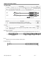
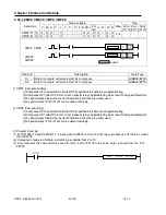
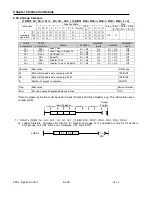
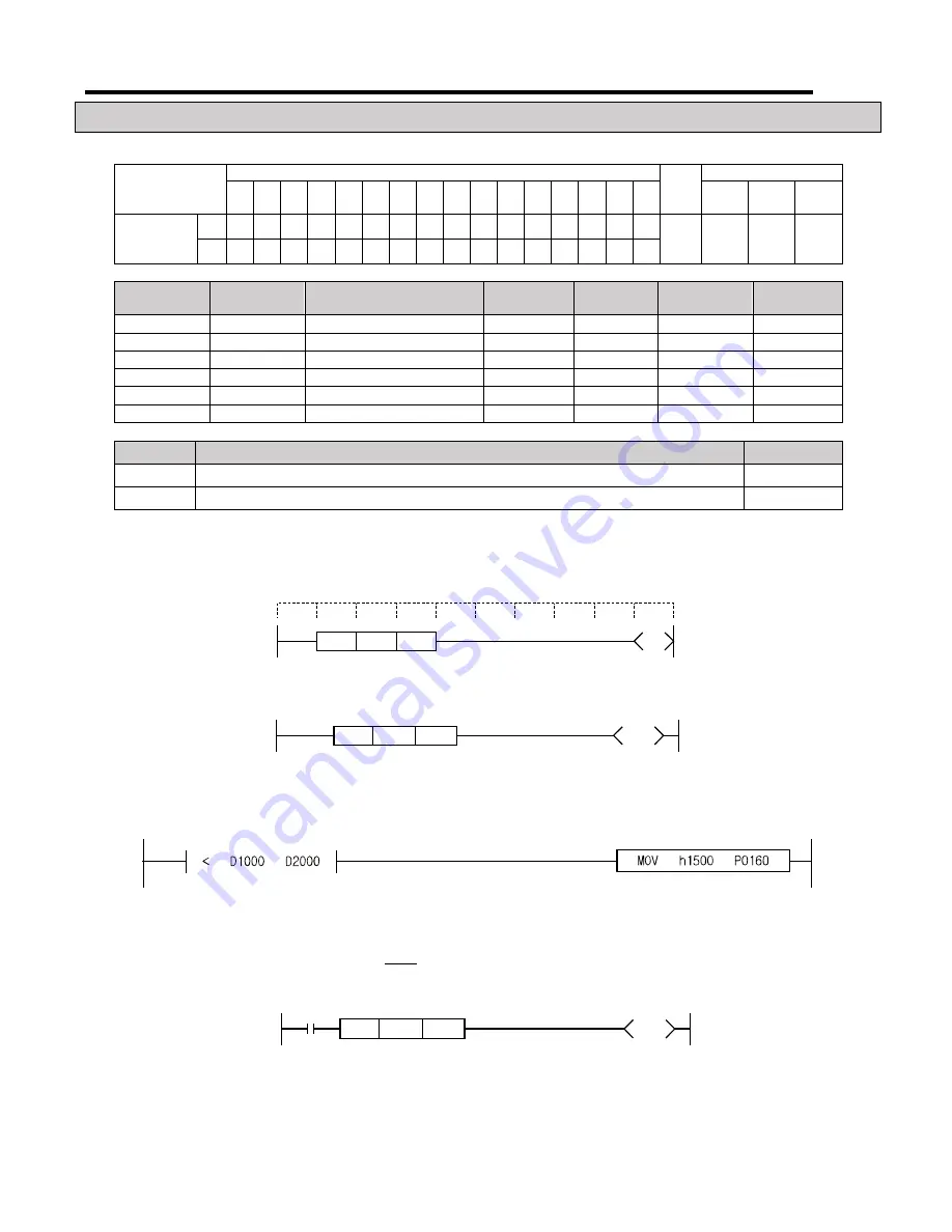
6.23 Compare Instruction, Signed (Input Position*)
6.23.1 Compare (16-Bit: <, <=, <>, =, >, >= ) (32-Bit: D<, D<=, D<>, D=, D>, D>=)
Instruction
Area Available
Step
Flag
P
M K
F
L
T
C
S
Z D.x R.x
Con
st.
U
N
D
R
Error
(F110)
Zero
(F111)
Carry
(F112)
x
(compare
operators)
S1 O O O O O O O
-
O
-
-
O O O O O
2~3
-
-
-
S2 O O O O O O O
-
O
-
-
O O O O O
16-Bit
x
Operators
32-Bit
x
Operators
Name
Condition
Operation
result
Condition
Operation
result
<
D<
Less Than
S1 < S2
On
S1
≥
S2
Off
<=
D<=
Less Than or Equal To
S1
≤
S2
On
S1 > S2
Off
<>
D<>
Not Equal To
S1
≠
S2
On
S1 = S2
Off
=
D=
Equal To
S1 = S2
On
S1
≠
S2
Off
>
D>
Greater Than
S1 > S2
On
S1
≤
S2
Off
>=
D>=
Greater Than or Equal To
S1
≥
S2
On
S1 < S2
Off
Operand
Description
Data Type
S1
First Data or Data address to compare
INT/DINT
S2
Second Data or Data address to compare
INT/DINT
*Note: Compare instruction must be used in Input (Contact) Position of ladder rung. This instruction uses 3
contact points.
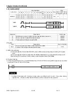
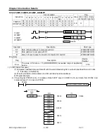
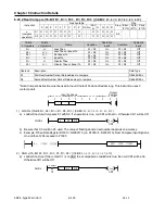
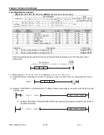
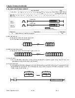
1) LOAD
x
(16-Bit: <, <=, <>, =, >, >= ) (32-Bit: D<, D<=, D<>, D=, D>, D>=)
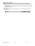
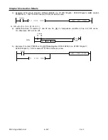
a) Ladder Structure: Compares S1 with S2. If
x
operation is true, coil CR1 will be On. Otherwise CR1 will be Off.
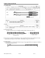
b) Example: When Data Register D1000=10 < D2000 (i.e when D1000=5; D2000=10), Compare Input Signal is
On and h1500 is saved in P0160 (I/O Device) area.
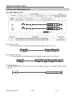
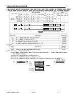
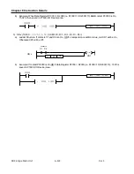
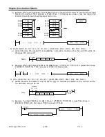
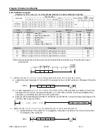
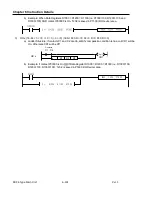
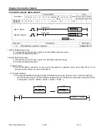
2) AND
x
(16-Bit: <, <=, <>, =, >, >= ) (32-Bit: D<, D<=, D<>, D=, D>, D>=)
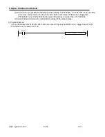
a) Ladder Structure: If contact C1 is On AND the
x
comparison condition is true, then coil CR1 will be On.
Otherwise CR1 will be Off.
x
S1
S2
LOAD
x
Coil
CR1
x
S1
S2
AND
x
Contact
Coil
CR1
C1
Input Positions
Output
Position
Содержание XBC-DN10E
Страница 1: ......
Страница 10: ...Table of Contents Table of Contents 6 10 10 CLEAR ALL PLC 29...
Страница 52: ...Chapter 3 Installation and Wiring XBC E Type Main Unit 3 24 Ver 1 3 7 2 XBC DR10E 4 point relay output...
Страница 54: ...Chapter 3 Installation and Wiring XBC E Type Main Unit 3 26 Ver 1 3 7 3 XBC DN10E 4 point transistor output...
Страница 56: ...Chapter 3 Installation and Wiring XBC E Type Main Unit 3 28 Ver 1 3 7 4 XBC DR14E 6 point relay output...
Страница 58: ...Chapter 3 Installation and Wiring XBC E Type Main Unit 3 30 Ver 1 3 7 5 XBC DN14E 6 point transistor output...
Страница 60: ...Chapter 3 Installation and Wiring XBC E Type Main Unit 3 32 Ver 1 3 7 6 XBC DR20E 8 point relay output...
Страница 62: ...Chapter 3 Installation and Wiring XBC E Type Main Unit 3 34 Ver 1 3 7 7 XBC DN20E 8 point transistor output...
Страница 64: ...Chapter 3 Installation and Wiring XBC E Type Main Unit 3 36 Ver 1 3 7 8 XBC DR30E 12 point relay output...
Страница 66: ...Chapter 3 Installation and Wiring XBC E Type Main Unit 3 38 Ver 1 3 7 9 XBC DN30E 12 point transistor output...